Level Measurement Instruments
Level measurement instruments are used to provide the exact level of liquids or solids in atmospheric or pressurized vessels, tanks or hoppers that can lead to calculate their weight or volume.
Level measurement instruments could be used for inventory control, custody transfer, leakage monitoring, overfill protection, batch control, dosing systems, mixed liquids separation and many other precise controls.
Level measurement instruments could be categorized as the following:
Level gauges are used for visual and local level indication in the field and level transmitters are used for continuous level monitoring and control from control room.
Level switches are usually used for protection controls.
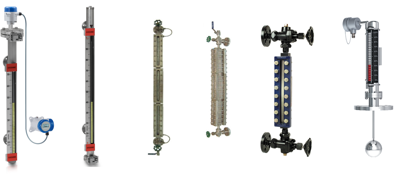
Level Gauge
The most common industrial types of level gauges are:
- Sight Glass
- Glass Level Gauge
- Magnetic Level Gauge
- Float Level Gauge
Sight Glass
Sight glass is a glass window or tube installed on a vessel or tank that allows the operator to observe the inside of that vessel or tank.
Operator might needs to observe liquid level or check the process inside of the vessel to ensure optimal quality or safety.
Sight glass could be in form of a glass disk with a flanged metal frame which will be installed on the vessel nozzle or could be a vertical tube with flange connections at top and bottom.
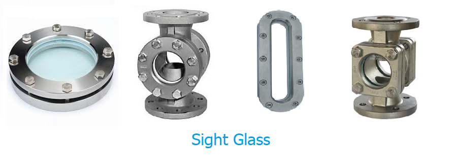
Tube sight glasses are similar to contemporary level gauges, but only provides level indication at a specific level or a very small range.
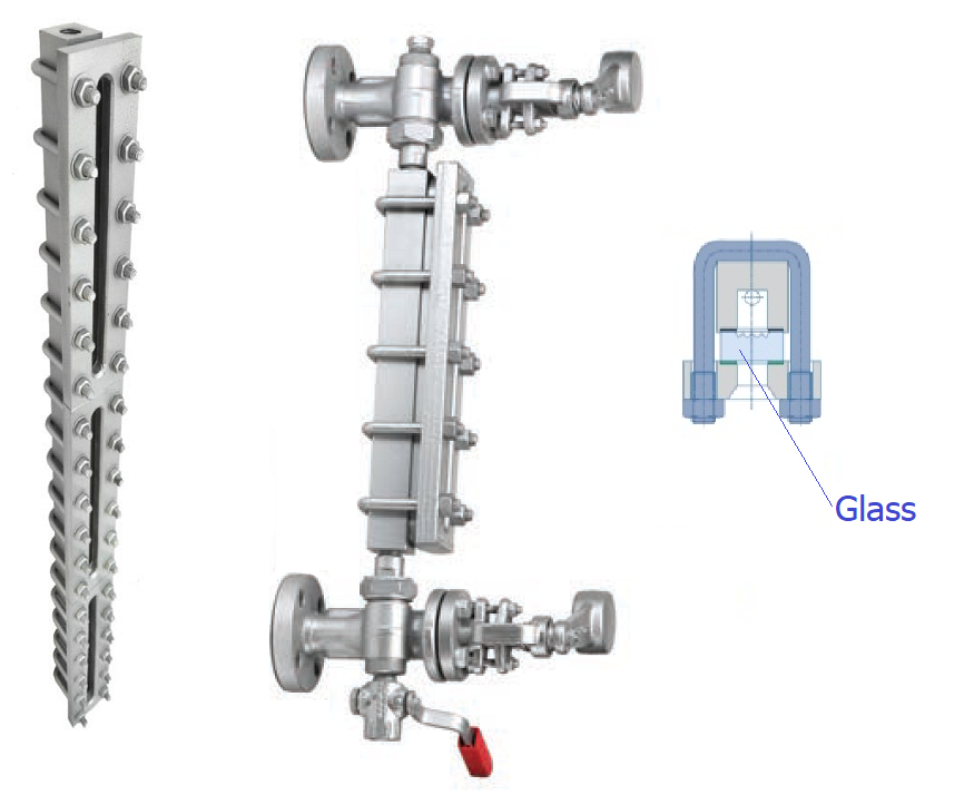
Glass Level Gauge
There are three types of level gauges; Reflex, Transparent and Bi-Color.
Glass Level gauges have four major parts; metal chamber, glass, two cock valves on top and bottom and two valves or plugs for drain and vent.
Tubular is another type of glass level gauge but is not applicable in industrial applications.
Reflex Level Gauge
Reflex Level Gauge works based on light reflection and refraction laws.
In Reflex Level Gauge, front of the metal chamber is covered with a glass that has prismatic grooves with section angle of 90° that forms an angle of 45° with the liquid.
When the liquid enters the gauge chamber, based on communicating vessels principle, its level in the gauge settles at the same level of liquid in the vessel or tank.
The liquid level is distinguished by different brightness of the glass between the liquid and gas/vapor zones, because of the difference in the refractive indices of liquid with gas/vapor.
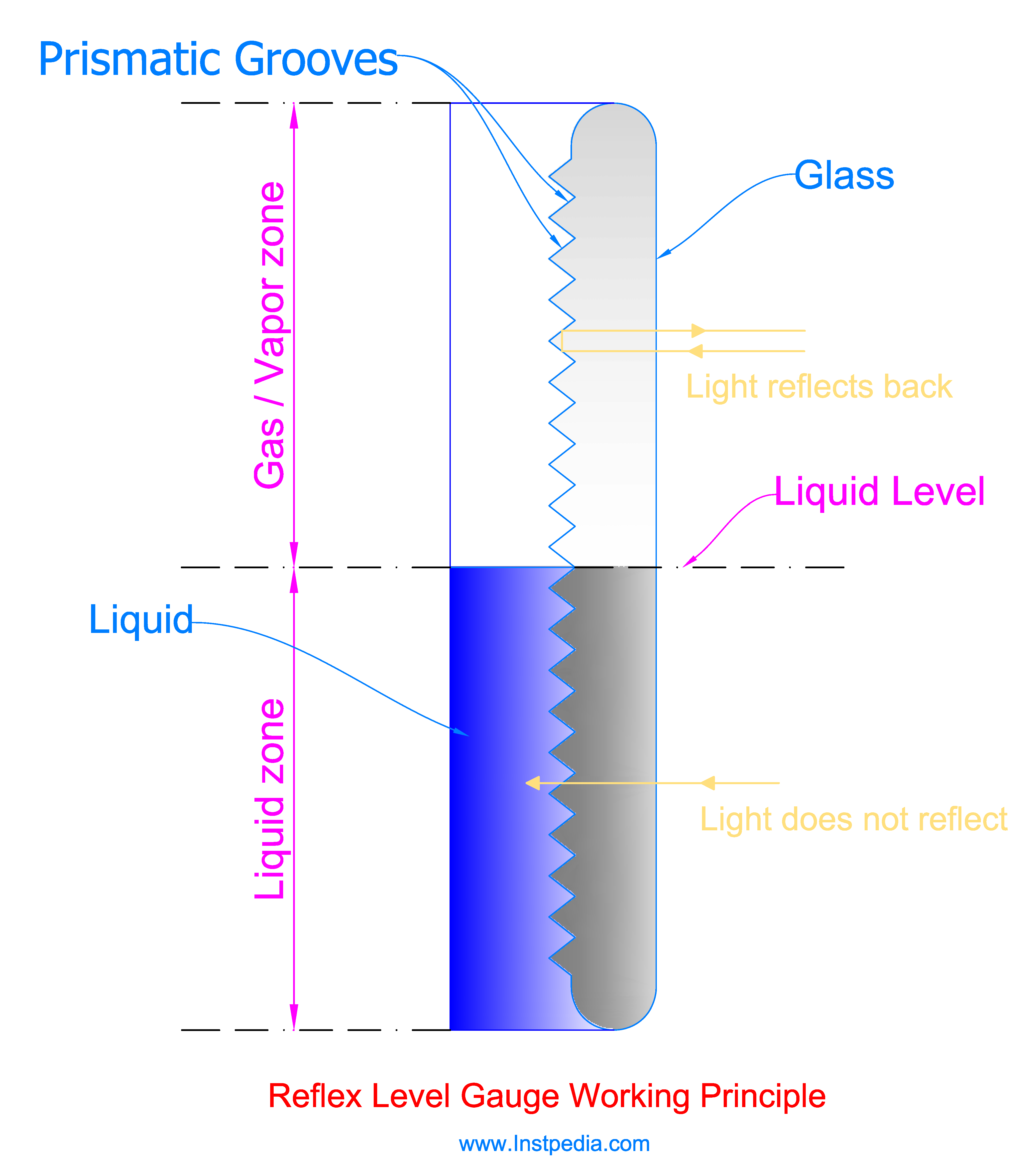
Gas/vapor region light reflection degree is less than 45°, therefore in gas/vapor region the light is reflected back to the glass surface so it appears silvery white.
In other words, the difference in the index of reflection between the gas/vapor and the glass is large, hence the light cannot pass the from the glass prismatic grooves and reflects back.
Liquid region light reflection degree is greater than 45°, so the light is not reflected back, therefore the glass appears darker in liquid region.
It means that due to small difference in the index of reflection between the glass and the liquid, the light passes through the prismatic area of the glass.
Reflex level gauge does not require illumination, and day light is sufficient for visualizing the liquid level.
Reflex Level Gauge Applications
Reflex Level Gauge is used for clean and clear liquids, and should not be used for steam or corrosive services, because using mica shield which is necessary for glass protection cannot be installed with prismatic glass.
Reflex Level Gauge is not suitable for services of two liquids with different densities because the interface level between the upper and lower liquids cannot be distinguished clearly.
Reflex Level Gauge could be used for C3 and lighter hydrocarbon if they are not dark and dirty.
Heavier hydrocarbons, dark or dirty liquids might coat the glass with a dark layer, hence the lower liquid levels could not be distinguished properly.
Transparent Level Gauge
Transparent Level Gauge has two flat glass panels in front and behind of the chamber.
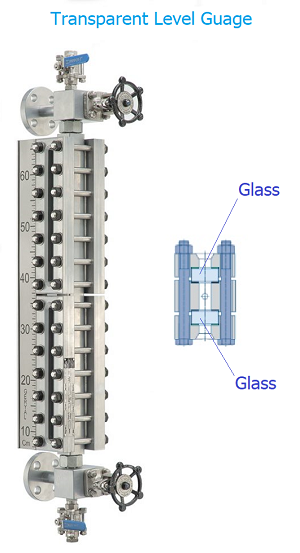
The light ray enters from the rear glass and passes through the fluid and exits from the front glass.
Difference between transparencies of mediums distinguishes the level.
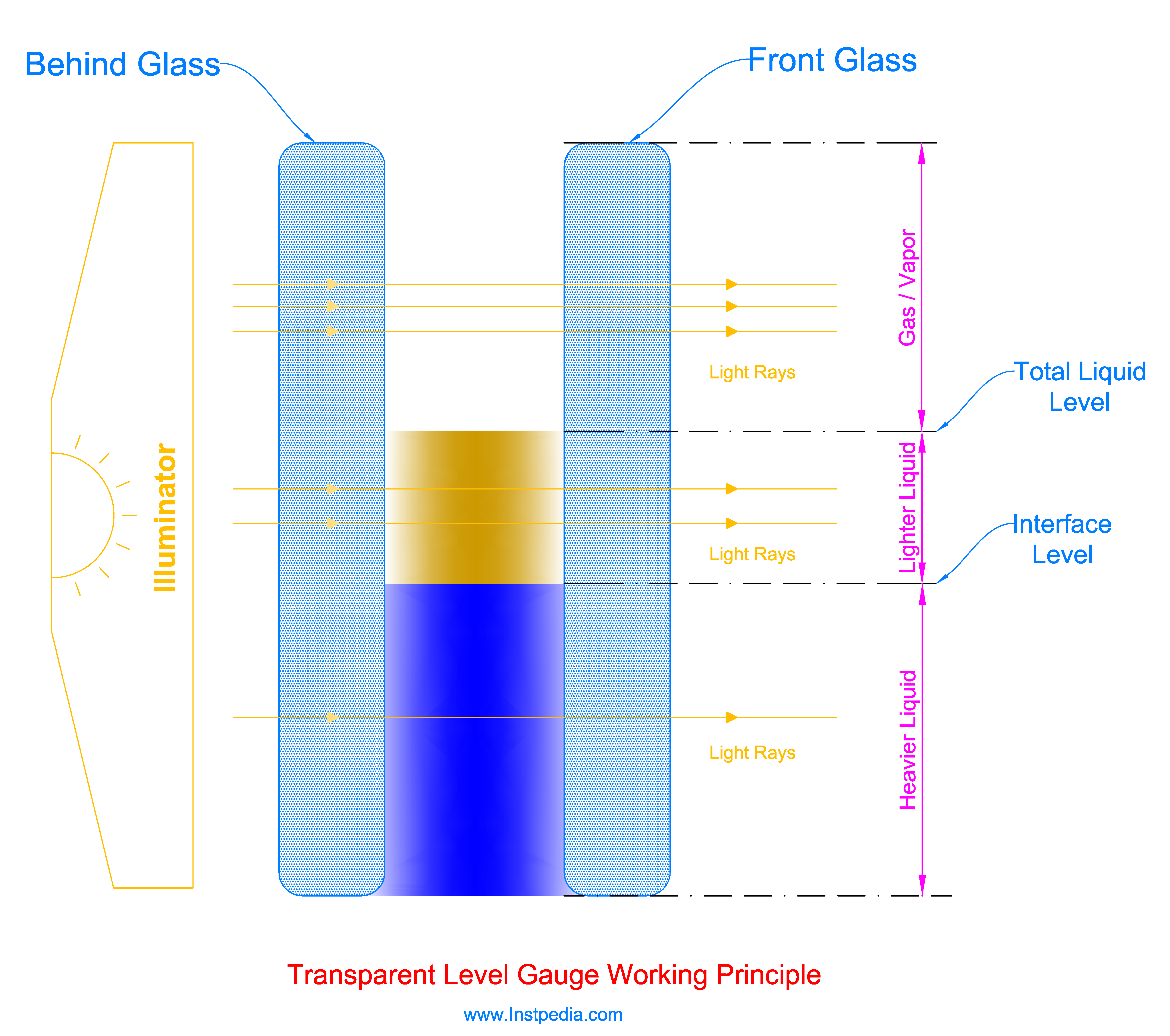
Usually, an illuminator is installed behind the gauge for better level indication.
Because liquids with different transparencies could be distinguished, transparent level gauge is used for indication of interface level between two liquids with different densities.
In order to protect the glass from steam, hot alkaline or acidic solutions, amines, hydrofluoric acid, caustic and other corrosive services, transparent level gauge should be equipped with mica shield as a protective film behind the glass.
Transparent level gauge illuminator should be suitable for the hazardous area classification of the installation area.
Transparent Level Gauge Applications
Transparent Level Gauge can be used for the following applications:
- Dirty or dark colored liquids
- Acid or caustic services
- Interface services
- Services with viscosity higher than 10 cP.
- Corrosive services where mica shield should be used
Bicolor Level Gauge
Bicolor Level Gauge is used for indication of condensate water and steam levels on high pressure boiler steam drums.
Bicolor Level Gauge indicates Water (lower part) in green and steam (upper part) in red.
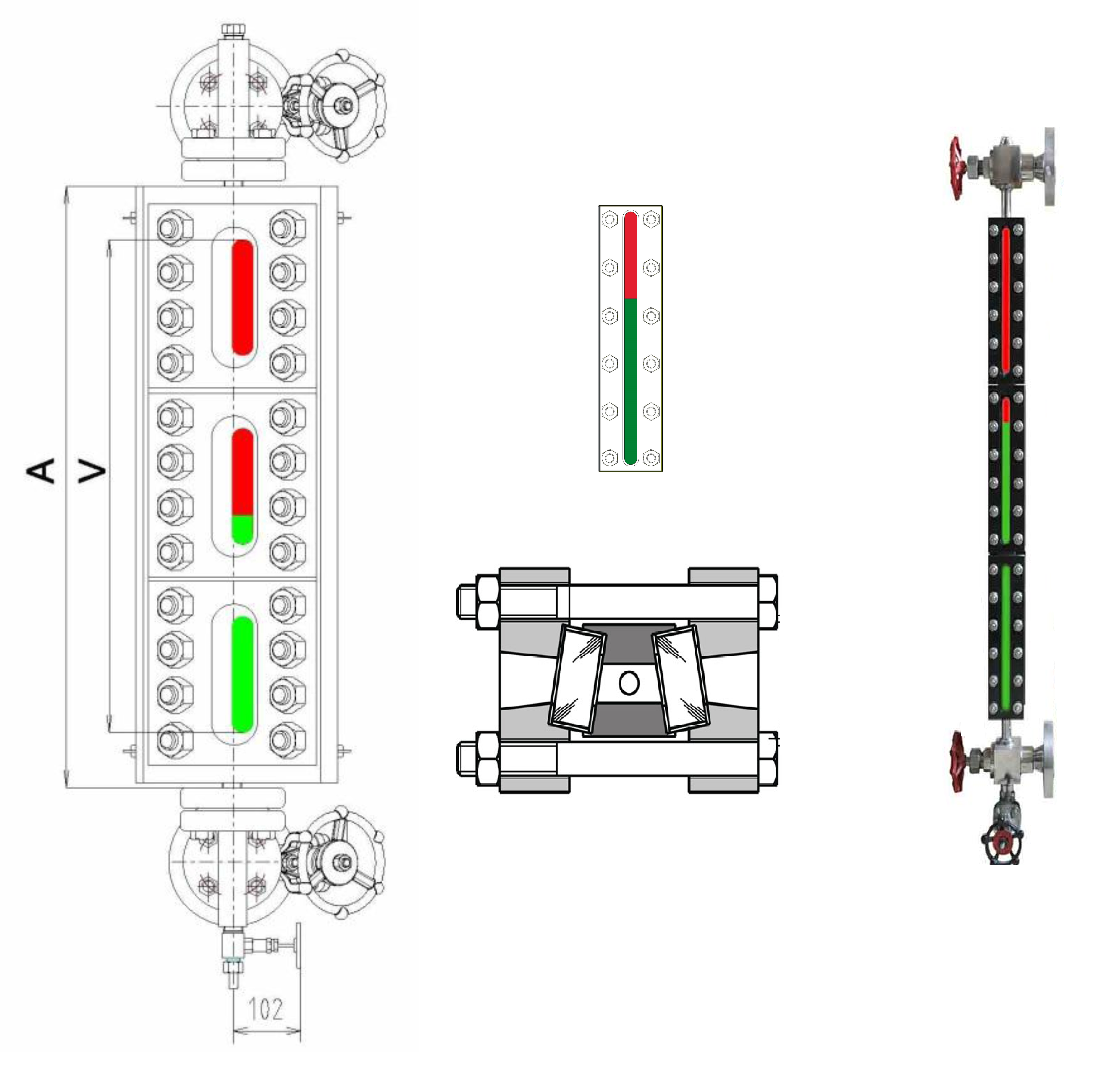
This instrument consists of a stainless steel body which has a trapezoid cross section, two glass sets in front and back of the body, a bicolor filter and an illuminator behind the back glass.
The glass faces are not parallel because of trapezoid cross section of the body.
A red and green filter is located behind the back glass that converts the illuminator light into red and green light rays.
Red rays and green rays have different index of refraction when passing obliquely through glass, water and steam.
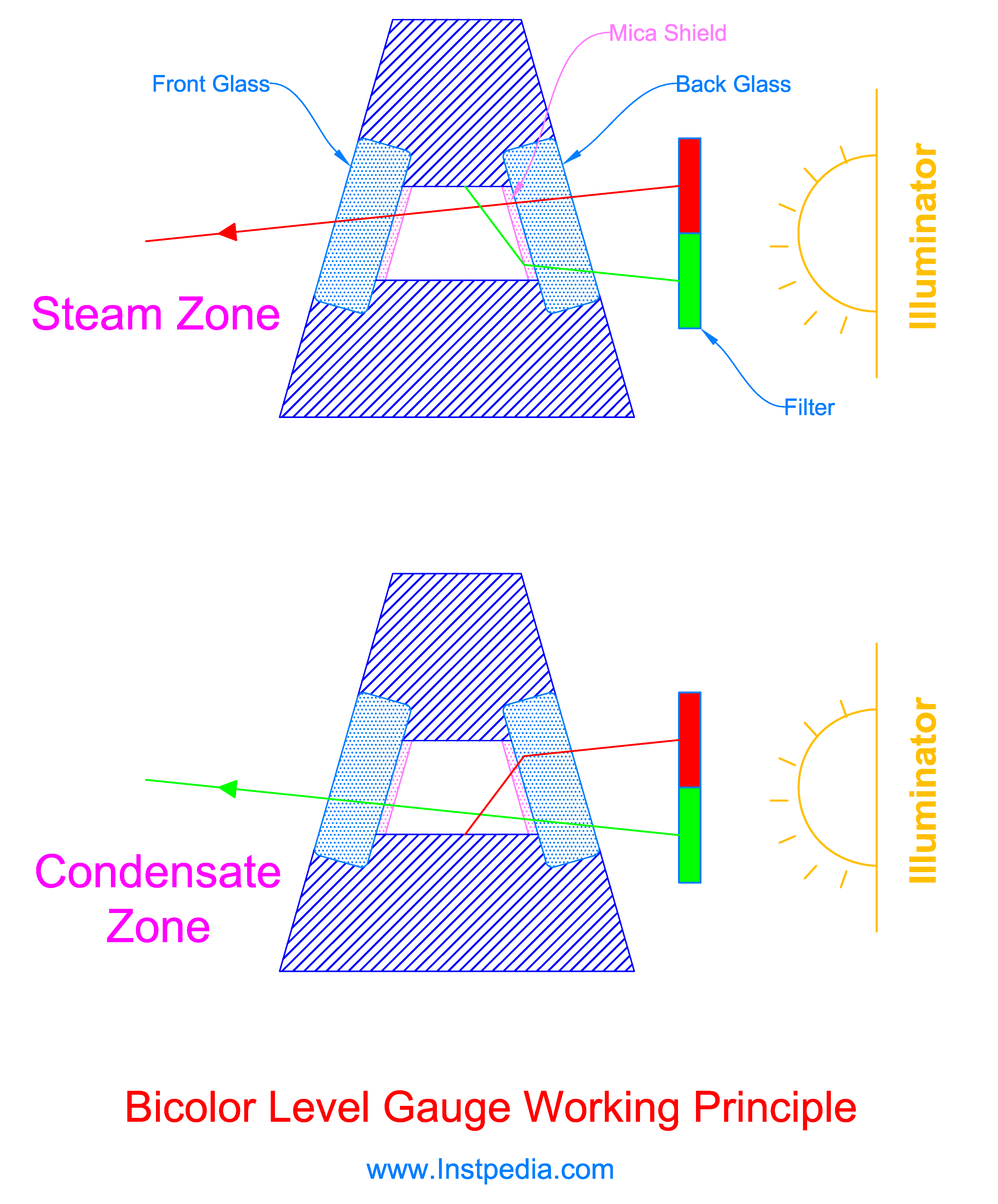
In lower part where water condensate is accumulated, the red rays are deviated, and because of non-parallel glasses could not pass through the front glass, but green rays can reach the front glass, therefore the observer sees this part of level gauge in green.
In upper part where contains steam, conversely the green rays are deviated and could not pass through the front glass, but red rays pass through the front glass, and this part of level gauge is observed in red.
Because of high temperature, front and back glasses are protected by mica shield.
Because bicolor level gauge is used for high pressure boiler steam drums, it should be designed in accordance with ASME BOILER AND PRESSURE VESSEL CODE - SEC. I. standard.
Bicolor level gauge illuminator should be suitable for the hazardous area classification of the installation area.
Glass Level Gauge Parts
Glass Level gauges have three major parts; metal chamber (Body) , glass and valves (two cock valves on top and bottom and two valves or plugs for drain and vent).
Level Gauge Body
Chamber, the metal part of the body, with the glass which is bolted and fastened to the chamber, form the whole gauge body.
Because of limitations in length of the glass, chambers are manufactured in standard lengths, based on standard sizes of the glass.
There are 9 standard sizes for glass, therefore there would be 9 sizes of body sections.
Manufacturers provide a table including the visible length and connections center-to-center (C-C) length relevant to different numbers of sections for each standard glass size.
In order to keep physical and mechanical strength of the level gauge, it is recommended not to use glass level gauge with C-C length of more than 2000mm.
If the required C-C length is more than 2000mm, then two or more level gauges with at least 50mm overlap in visible length could be used.
Body material is usually ASTM A105 carbon steel for noncorrosive services, but for corrosive and cryogenic services ASTM A316 stainless steel is the best solution.
For services that contain an aggressive species such as chloride (Cl-) like seawater, Hastelloy C which is Nickle based alloy with molybdenum content or Duplex or Superduplex alloys could be the suitable materials for body.
Level Gauge Glass
Strength of glass decreases by increase in length; therefore, the glass length could not be as long as the measuring length.
Therefore, the gauge chamber should be constructed by connecting definite numbers of standard sections proportional to standard glass sizes to provide the gauge visible length.
There are 9 standard sizes for glass from 115mm to 340mm.
| Standard Sizes for Level Gauge Glass | |||||||||
|---|---|---|---|---|---|---|---|---|---|
| Size | 1 | 2 | 3 | 4 | 5 | 6 | 7 | 8 | 9 |
| Length (mm) | 115 | 140 | 165 | 190 | 220 | 250 | 280 | 320 | 340 |
Size 9 is the most common glass size, used in industrial applications.
Glasses are available in three widths of 34mm,30mm and 25mm, but 34mm is the standard width for level gauges glass.
The glass is the weak point of level gauge and should be manufactured from special materials that could withstand the industrial temperature and pressure conditions.
Tempered glass is the most frequent glass used for level gauges which is thermally and physically stronger than normal glass due to special thermal and chemical treatments.
Borosilicate glass is a kind of tempered glass which is manufactured from silica and boron trioxide in high temperature.
Borosilicate glass has a very low thermal expansion coefficient and has the best chemical resistance to acidic solutions also is very resistant to sudden temperature changes, but is less resistant to alkaline solutions.
Borosilicate glass could be used for services with temperature up to 315 ℃.
Aluminosilicate glass that contains aluminum oxide is more heat resistant that can tolerate temperatures up to 425℃, and has higher pressure rating and better chemical resistance especially to alkaline solutions in comparison to Borosilicate glass.
Quartz which is made by fusing quartz crystals is more abrasive resistant material than glass and can be used for services with temperature up to 560℃, but it is more brittle.
Level Gauge Glass Protection
In order to protect the glass from steam, hot alkaline or acidic solutions, amines, hydrofluoric acid, caustic, and other corrosive services, transparent level gauge should be equipped with a protective film.
Mica shield is the best and most frequent protective film used for transparent level gauges.
Mica shield is not applicable for reflex level gauges, because of the prismatic grooves on inner side of the glass.
Mica is natural silicate (phyllosilicate) mineral and has extremely high temperature resistant, good transparency and clarity, acceptable flexibility and corrosion resistance against hot alkaline or acidic solutions.
Mica has different grade from V1 to V10 for different applications, but there are two mica grades that are suitable for level gauges glass protection:
V2 Ruby/Green Clear and Slightly Stained
V2 Clear and Slightly Stained mica grade is hard, and has uniform color, but may contain slight crystallographic discoloration, and is free from all vegetable and mineral stains, cracks, buckles, other similar defects.
It is also free from foreign inclusions except for a few tiny air inclusions in not more than one-fourth of the useable area.
This grade is suitable for steam services from 600 to 1500 PSI (41 to 103 bar).
It is available in two color groups; ruby and green.
V4 Ruby/Green Good Stained
V4 Good Stained mica grade is hard, and has uniform color, but may contain slight crystallographic discoloration, and is free from vegetable and mineral stains, cracks, buckles and other similar defects.
It is also free from foreign inclusions, except somewhat wavy but not rippled, and may contain some air inclusions in not more than two-thirds of the usable area.
This grade is suitable for steam services from 300 to 600 PSI (20 to 41 bar).
It is available in two color groups; ruby and green.
Standard mica shield sizes and thicknesses are as the following tables:
| Standard Mica Shield Sizes (mm) | ||||
|---|---|---|---|---|
| No | Mica Shield (Type A/B) | Mica Shield (Type A) | Mica Shield (Type B/H) | Mica Shield (Type TA-28) |
| Length x Breadth | Length x Breadth | Length x Breadth | Length x Breadth | |
| 0 | 95 x 24 | 95 x 30 | 95 x 34 | 133 x 47 |
| I | 115 x 24 | 115 x 30 | 115 x 34 | 158 x 47 |
| II | 140 x 24 | 140 x 30 | 140 x 34 | 183 x 47 |
| III | 165 x 24 | 165 x 30 | 165 x 34 | 208 x 47 |
| IV | 190 x 24 | 190 x 30 | 190 x 34 | 238 x 47 |
| V | 220 x 24 | 220 x 30 | 220 x 34 | 268 x 47 |
| VI | 250 x 24 | 250 x 30 | 250 x 34 | 298 x 47 |
| VII | 280 x 24 | 280 x 30 | 280 x 34 | 338 x 47 |
| VIII | 310 x 24 | 320 x 30 | 320 x 34 | 358 x 47 |
| IX | 320 x 24 | 340 x 30 | 340 x 34 | 378 x 47 |
| X | 340 x 24 | 370 x 30 | 370 x 34 | |
| XI | 360 x 24 | 400 x 30 | 400 x 34 | |
| XII | 370 x 24 | 430 x 30 | 430 x 34 | |
| XIII | 400 x 24 | 460 x 30 | 460 x 34 | |
| XIV | 430 x 24 | 500 x 30 | 500 x 34 |
| Standard Mica Shield Thicknesses (mm) | |||||
|---|---|---|---|---|---|
| 0.10 - 0.15 | 0.13 - 0.17 | 0.15 - 0.20 | 0.18 - 0.22 | 0.20 - 0.30 | 0.30 - 0.40 |
For Hydrofluoric Acid services primarily, PCTFE shields (Kel-F ®) are used which can operate in temperature range of -240℃ up to 150℃.
Level Gauge Valves
Glass Level gauge is connected to the vessel or tank with two cock valves at top and bottom of the level gauge.
Cock valve is an angle valve that the angle between the inlet and outlet of the valve is 90 deg.
The outlet of the cock valve which is connected to the vessel nozzle is usually flanged.
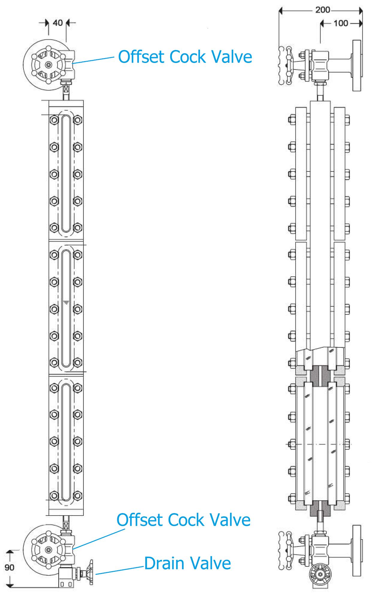
Cock valve connection to the level gauge is normally 1/2" or 3/4" NPTF thread connection, but 3/4" NPTF is preferred due to blocking risk reduction.
The top cock valve has another 1/2" connection for vent plug or vent valve.
Similarly, the bottom cock valve has a 1/2" connection for drain plug or drain valve.
Using plug for vent / drain is an economical solution, but after years of operation and maintenance it becomes the level gauge and vessel weak point and leakage source.
Therefore, it is recommended to select 1/2" vent /drain valve instead of plug.
Cock valve should be offset type in which the valve stem has an offset to the gauge body axis in order to allow glass cleaning with bottle brush without opening the cock valve and removing the level gauge.
But the offset could be left-handed or right-handed which needs to be defined before order in data sheet, considering the level gauge nozzles location on the vessel and the access point or ladder location.
Also, if the top cock valve is a right-handed offset valve, then the bottom cock valve should be left-handed offset valve.
This problem could be solved by selecting a rotatable head cock valve which could be installed at left side or right side of the gauge body during installation.
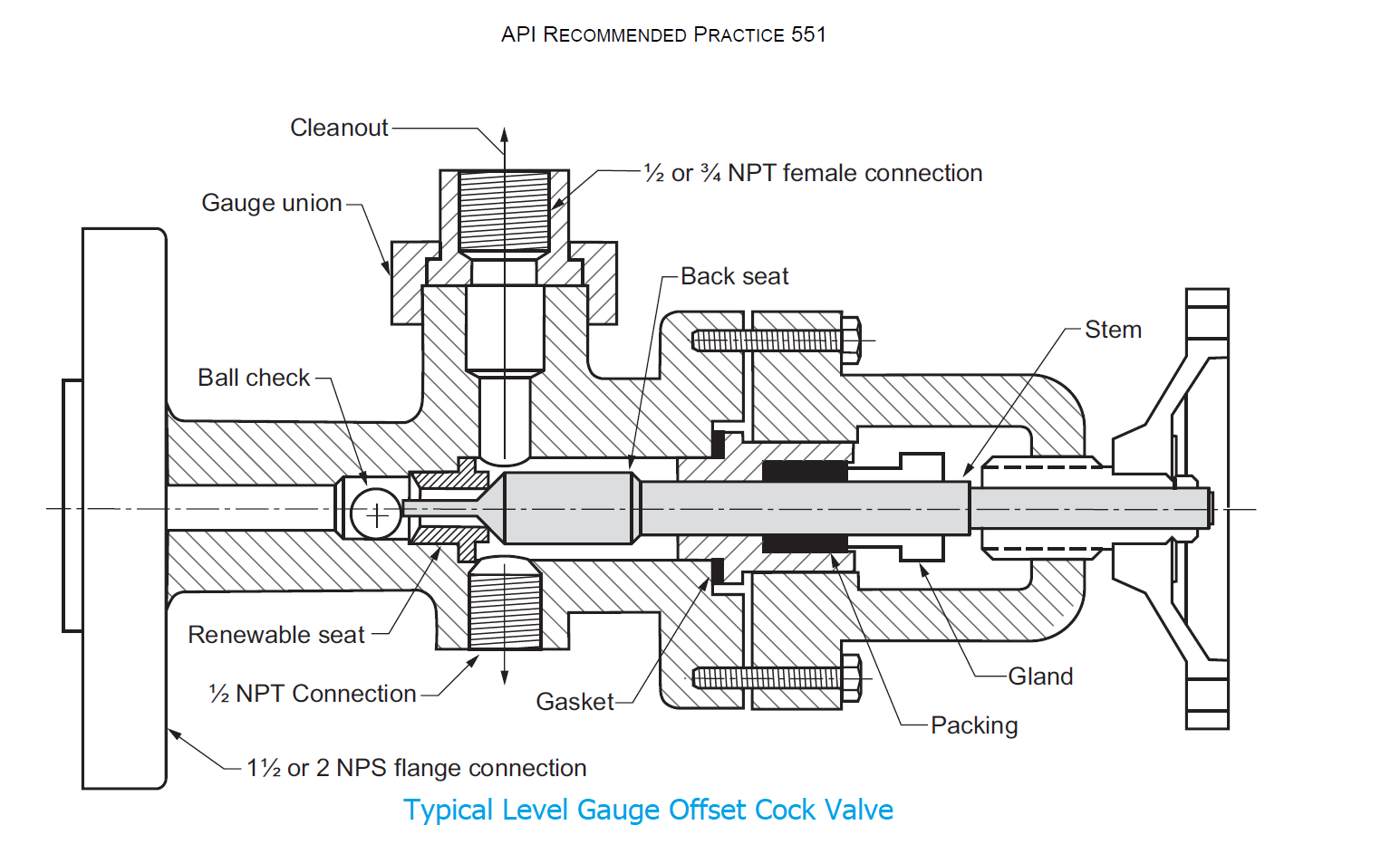
Cock valves should be equipped with a safety device which is called ball check.
Ball check prevents vessel content loss in case of level gauge failure which could be leakage or glass break.
In case of level gauge failure, the level gauge pressure decreases and the vessel liquid content tends to move inside the level gauge and bushes the ball check to cock valve seat, hence the level gauge entry will be blocked.
According to ASME BOILER AND PRESSURE VESSEL CODE - SEC. I. standard, ball check is not necessary for glass level gauges on boiler drums , because in prevents steam passing through the gauge during periodic steam blowdown.
Otherwise for steam applications, it should be vertical rising ball check and equipped only for the bottom cock valve.
Cock valve body due to small size is usually forged material and its metallurgy should be the same as level gauge body material.
For example, if the body material is cast carbon steel, ASTM A216 WCB, the cock valve material should be the equivalent forged carbon steel, ASTM A105.
Cock valve plug, needle, seat, stem and ball check should be AISI 316 Stainless steel or better.
Level Gauge Illuminator
Transparent and bicolor level gauges require illuminator.
Contemporary illuminators are LED illuminators, but incandescent bulbs and fluorescent lamps were the most frequent used illuminators.
Incandescent bulbs and fluorescent lamps require a plastic diffuser in order to spread the light across the gauge.
LED illuminators have low power consumption and longer life cycle.
| Illuminator Type | Incandescent Bulb | Fluorescent Lamp | LEDs |
|---|---|---|---|
| Life Cycle | 1000 hr | 15000 hr | 100000 hr |
Therefore, Incandescent bulb and fluorescent lamp illuminators could be equipped with a spring return power switch to ensure that the illuminator is turned off after use for longer life time and minimum maintenance.
LED illuminators have a long-life cycle and more reliability, because if a LED fails the nearby LEDs lighting overlap, covers the failed LED area.
Illuminator in hazardous areas should be explosion proof.
Electrical department is responsible for providing the required electrical power for illuminators; hence this department needs to be informed about operating voltage type and level, power consumption and location of the illuminators.
Glass Level Gauge Installation
Strength of glass decreases by increase in length; therefore, the glass length could not be as long as the visible length.
Therefore, the gauge chamber should be constructed by connecting definite numbers of standard sections proportional to standard glass sizes to provide the gauge visible length.
As mentioned formerly, there are 9 standard sizes for glass from 115mm to 340mm.
| Standard Sizes for Level Gauge Glass | |||||||||
|---|---|---|---|---|---|---|---|---|---|
| Size | 1 | 2 | 3 | 4 | 5 | 6 | 7 | 8 | 9 |
| Length (mm) | 115 | 140 | 165 | 190 | 220 | 250 | 280 | 320 | 340 |
Size 9 is the most common glass size, used in industrial applications.
The following table provides recommend number of sections and sizes for different visible lengths:
| No. of Sections | Glass Size | Level Gauge Size | Visible Length (mm) | Approximate C-C Length (mm) |
|---|---|---|---|---|
| 1 | 9 (340mm) | 1x9 | 320 | 600 |
| 2 | 9 (340mm) | 2x9 | 680 | 950 |
| 3 | 9 (340mm) | 3x9 | 1040 | 1300 |
| 4 | 9 (340mm) | 4x9 | 1400 | 1650 |
| 5 | 9 (340mm) | 5x9 | 1760 | 2000 |
Level gauge visible length should cover the measuring levels of all the level transmitters and switches on a vessel or tank.
It is recommended to select the visible length of level gauge to be 50mm higher than the highest measuring level (HH) and 50mm lower than the lowest measuring level (LL).
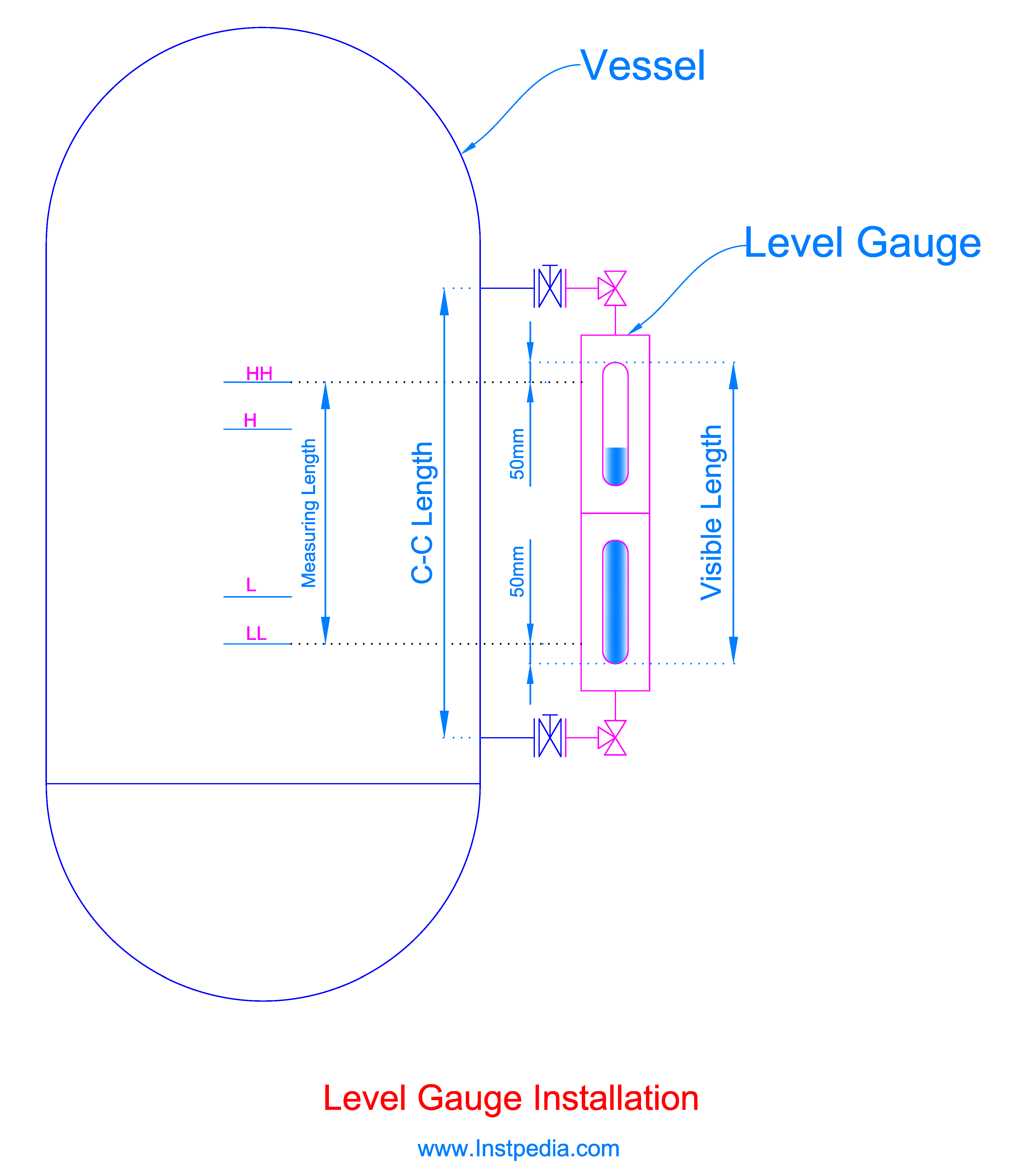
After selecting the visible length of the level gauge approximate C-C length could be derived from the above table or the manufacturer catalogue.
In order to keep physical and mechanical strength of the level gauge, it is recommended not to use level gauge with C-C length of more than 2000mm.
If the required C-C length is more than 2000mm, then two or more level gauges with at least 50mm overlap in visible length could be used.
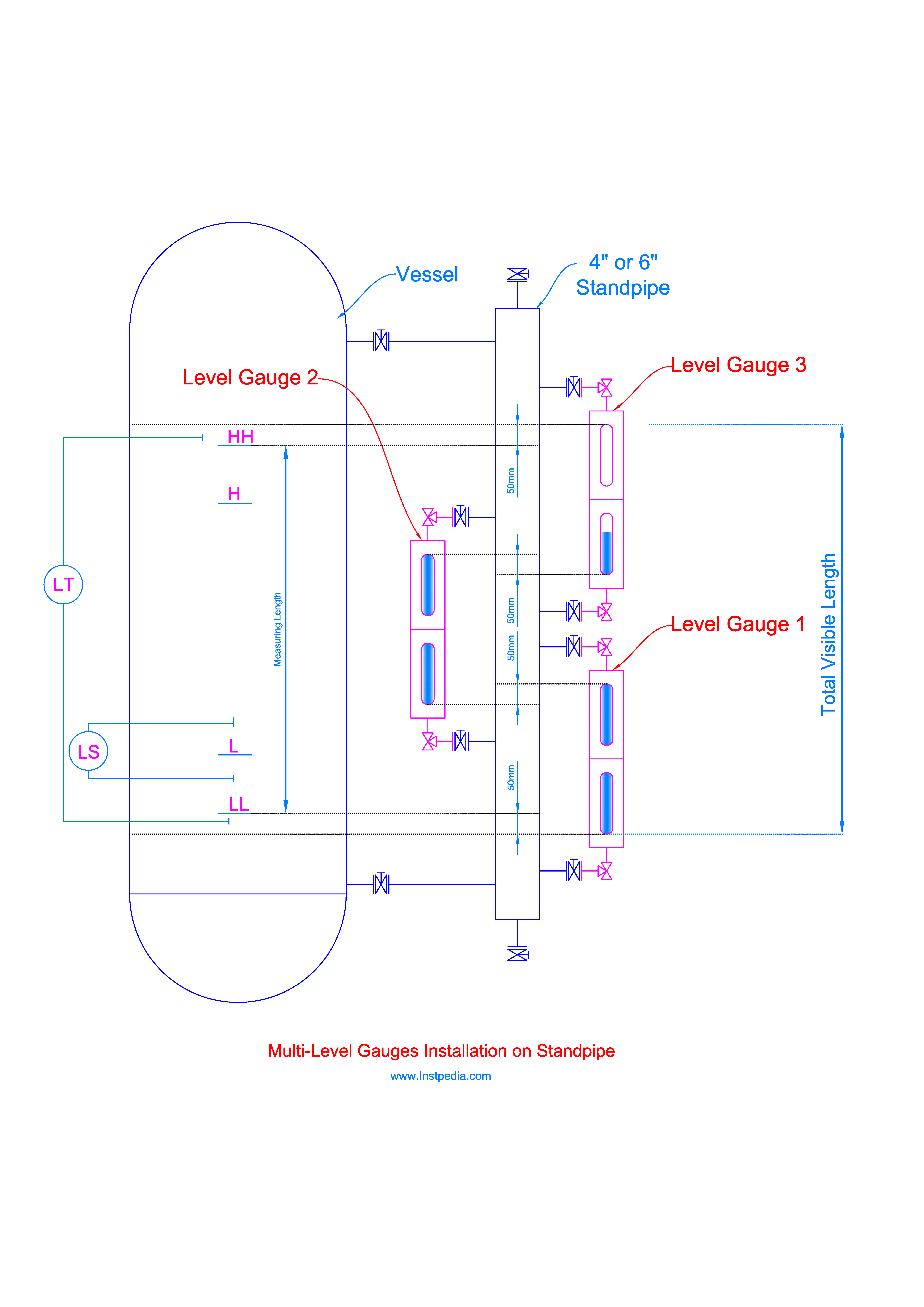
But using two or more level gauges requires more nozzles on the vessel which could affect its mechanical strength and could become a weak point.
Therefore, installation of a standpipe beside the vessel or tank for the two or more level gauges is an appropriate design.
Standpipe diameter could be 4" or 6" and it should be equipped with isolating valve.
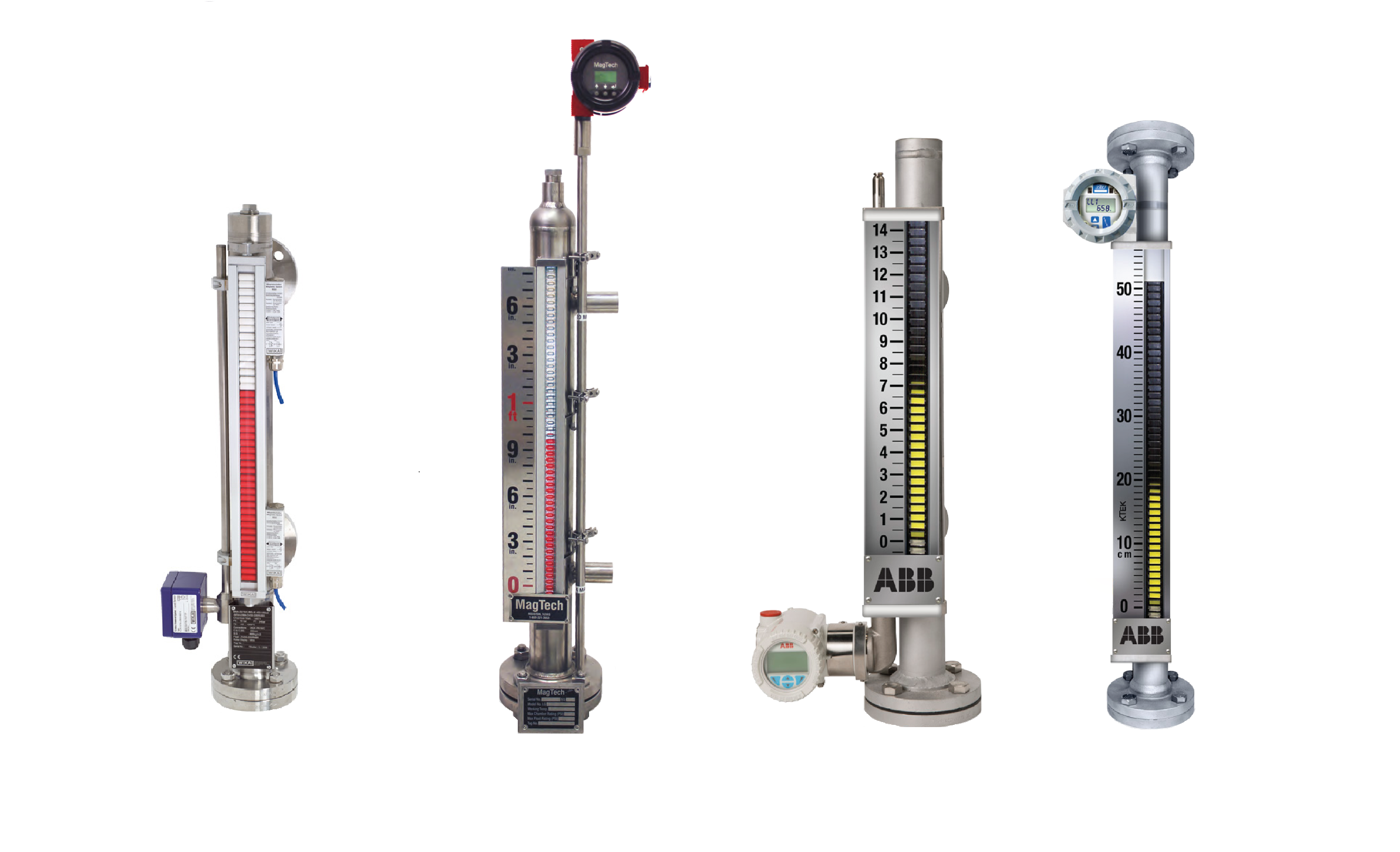
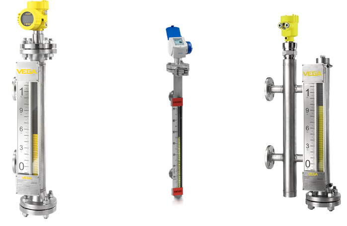
Magnetic Level Gauge
Magnetic Level Gauge consists of a float with permanent magnets inside a non-magnetic metal chamber and an indicator with rotating magnetic flags.
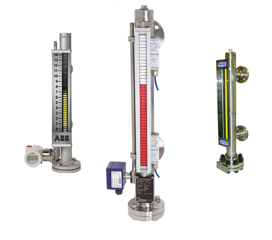
Magnetic Level Gauge does not have glass, therefore it does not have length limitation of glass level gauges, and can be used in higher pressure and temperature applications.
Another advantage of magnetic level gauge in comparison to glass level gauges is that the level can be visible from far distance.
Magnetic Level Gauge Applications
- High temperature or high pressure services that glass might fail
- Liquified C4 and lighter hydrocarbons which are colorless and flammable
- Flammable services where fire hazard exists in case of glass failure
- Dirty or viscose services that glass becomes coated and loses its transparency
- Interface level indication especially on separator drums
- Very corrosive or acidic services
- Cryogenic services
Magnetic Level Gauge Working Principle
Liquid level in the chamber of magnetic level gauge is the same as the vessel, based on the principle of communicating vessels.
The float will be remaining buoyant on the liquid's surface based on positive buoyancy.
There is a magnetic assembly inside of the float, and when float moves up and down with level on the liquid's surface, it rolls a series of rotating bi-color magnetic flaps or flags on an indication case which is fastened to the chamber.
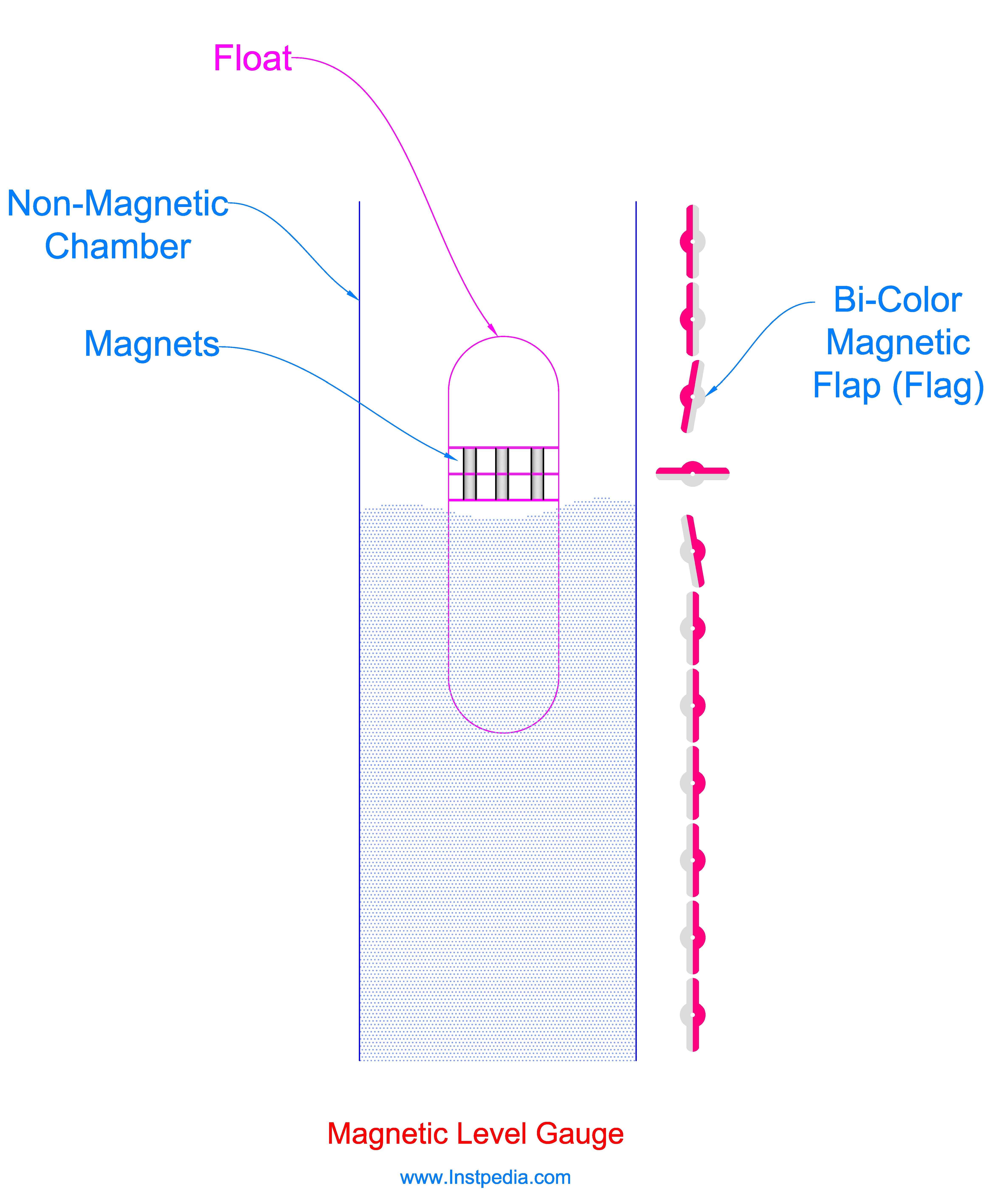
As a result, the indicator color from the liquid's surface level to the bottom is different from liquid's surface level to the top.
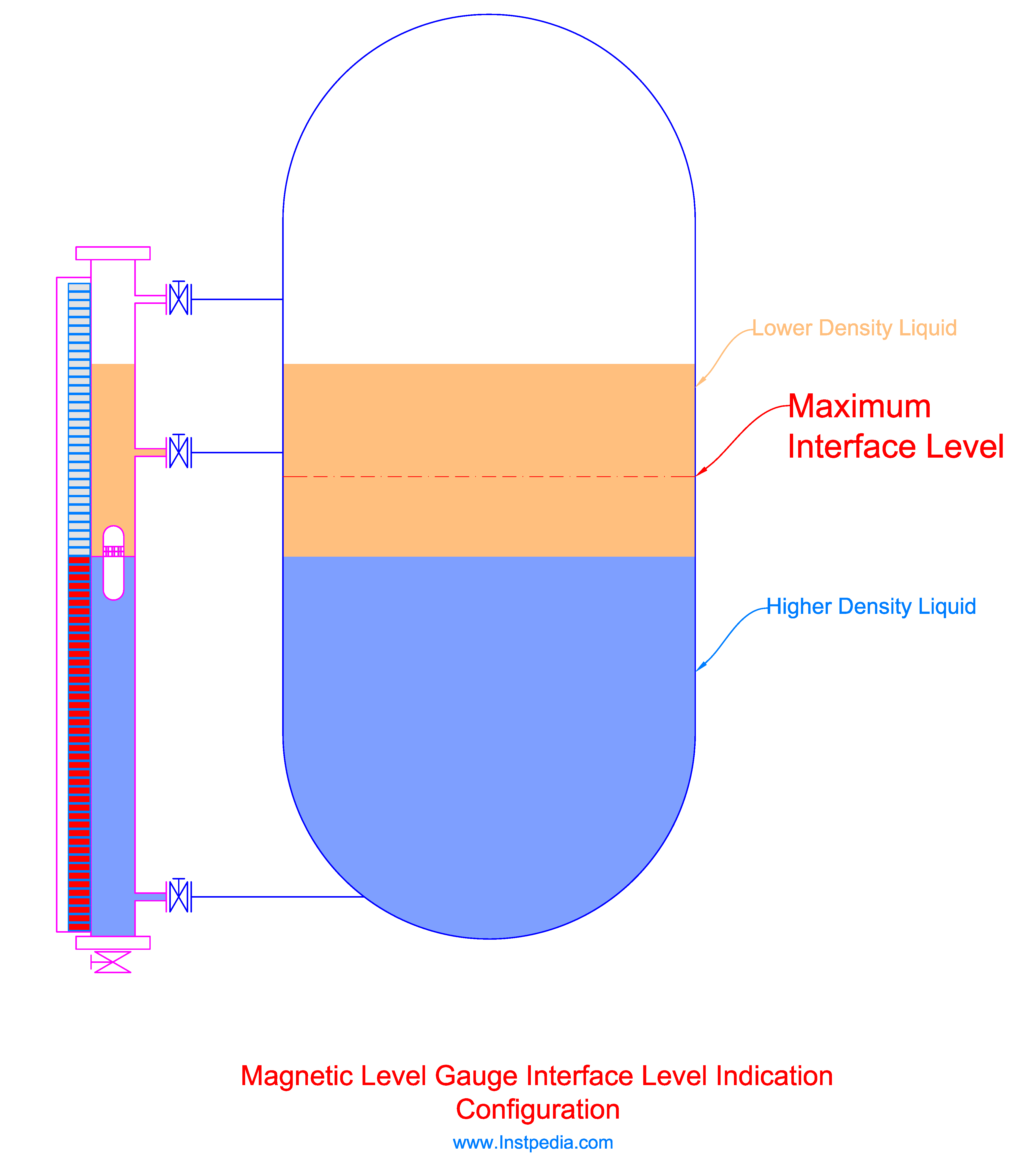
Magnetic level gauge could be used for interface level indication, too.
In this case float will be designed considering the lower liquid density in a way that, it remains buoyant on the heavier liquid's surface which is the interface level.
Magnetic Level Gauge Chamber
Magnetic Level Gauge Chamber is a standpipe with minimum diameter of NPS 2 with Schedule of 40.
NPS (Nominal Pipe Size) is an American standard for pipe size.
NPS 2 is equivalent to European standard pipe size, DN 50, and identical with 60.33mm.
Pipe schedule describes the pipe wall thickness and Sch.40 determines 3.912mm wall thickness for PNS 2 pipe.
Chamber material must be from non-magnetic metal that could pass the magnetic field of the float
Austenitic Stainless Steels (316SS, 304SS …) are non-ferrous stainless steels and can pass magnetic field.
AISI 316 / 316L Stainless Steels are the best and the most common material for chamber material due to proper resistance against corrosive services and acceptable mechanical properties with temperature range of -254 to 816°C.
For services that contain an aggressive species such as chloride (Cl-) like seawater, 316SS or 316L SS could not be used and Hastelloy C which is a Nickle Alloy with PREN (Pitting Resistance Equivalent Number) greater than 40 is recommended for such services but the price is considerable.
In order to provide the possibility of float replacement, the bottom of the chamber has a flanged connection.
A flanged valve could be used at the bottom of the chamber to drain the gauge during the maintenance.
It is recommended not to use drain plug instead of drain valve, because plug threads are subject to wear due to several opening and closing and could become a leakage point.
There should be a vent plug or valve at the top of the chamber to vent the accumulated gases; vent plug is an economic selection.
If the magnetic level gauge is used in boiler service the chamber should be designed according to ASME B31.1 and B31.3.
For other applications on pressurized vessels, the chamber should comply with ASME B&PV Code, Section VIII, Division 1.
For interface level indication application, the chamber should have more connections to the vessel in addition to the top and bottom connections and at least one of the connections should be higher than the interface level, otherwise the lighter liquid might be trapped inside the vessel and could not enter the chamber.
Chamber should be equipped with stop springs at the bottom and top of the chamber to avoid hard impact between float and the chamber, during fast drain or fast level increase.
Magnetic Level Gauge Float
The float is designed based on process pressure, temperature, fluid's specific gravity and fluid's corrosivity.
The magnetic assembly inside of the float rolls the magnetic bi-color flaps or flags of the indicator as the float rises and falls with liquid's level.
The magnetic assembly should be placed in the float in such a way that the indicated level coincides with the actual liquid's level.
The float length should be less than 250mm.
The float material should be non-magnetic material so that it could pass the magnetic field of magnetic assembly inside the float.
Process temperature is very important for selecting material for magnet assembly and designing the float.
The fluid temperature should not be above the magnet's Curie temperature.
Curie temperature (TC), is the temperature that magnetic materials lose their permanent magnetic properties above that temperature.
For application with operating temperature above 150 ℃, high temperature magnets should be used.
Please note that the float must be removed from the chamber before hydrostatic test of the vessel.
After the hydrostatic test special care should be taken for reinstallation of the float as the following:
- Float serial no. must be checked, because float is designed exclusively for each level gauge according to liquid specific gravity
- Float should not be installed upside down
- First, top isolating valve should be opened slowly for pressure equalization, then bottom valve in order to fill the chamber gradually
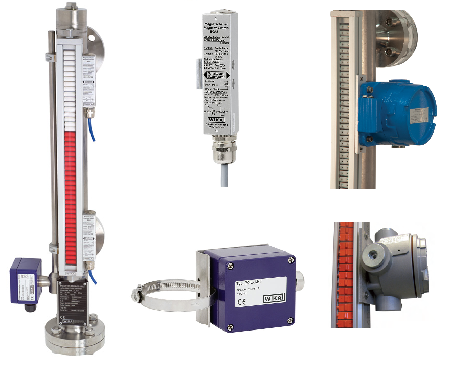
Magnetic Level Gauge Indicator
Indicator consists of a column of magnetic bi-color flags or rollers in a nonmagnetic case which is fastened or clamped to the chamber.
Alongside with the flags column there is a stain less steel scale marked usually with 10mm divisions.
Flaps color is usually yellow/black or red/white.
Indicator is not in contact with the medium; its case could be made of aluminum alloys even for corrosive applications, but in case of aggressive and harsh environment conditions stainless steel case is recommended.
The flags columns should be hermetically sealed in order to be protected from dost or condensation in humid environments.
The flags column design should prevent over rotation of flags due to fast level changes or vibration; it could be provided with mechanical stop or magnetic interlock.
Magnetic level switches can be clamped to the indicator in order to provide discreate signals as alarms or trips at specific levels.
There is another type of indicator which consists of a magnetic follower in a transparent tube instead of bi-color flags that rises and falls with floater movements in the chamber.
This type of indicator is not recommended for applications with high vibration or fast liquid level changes, because in those applications follower might be decoupled from the float, also the follower cannot be visible from far distance.
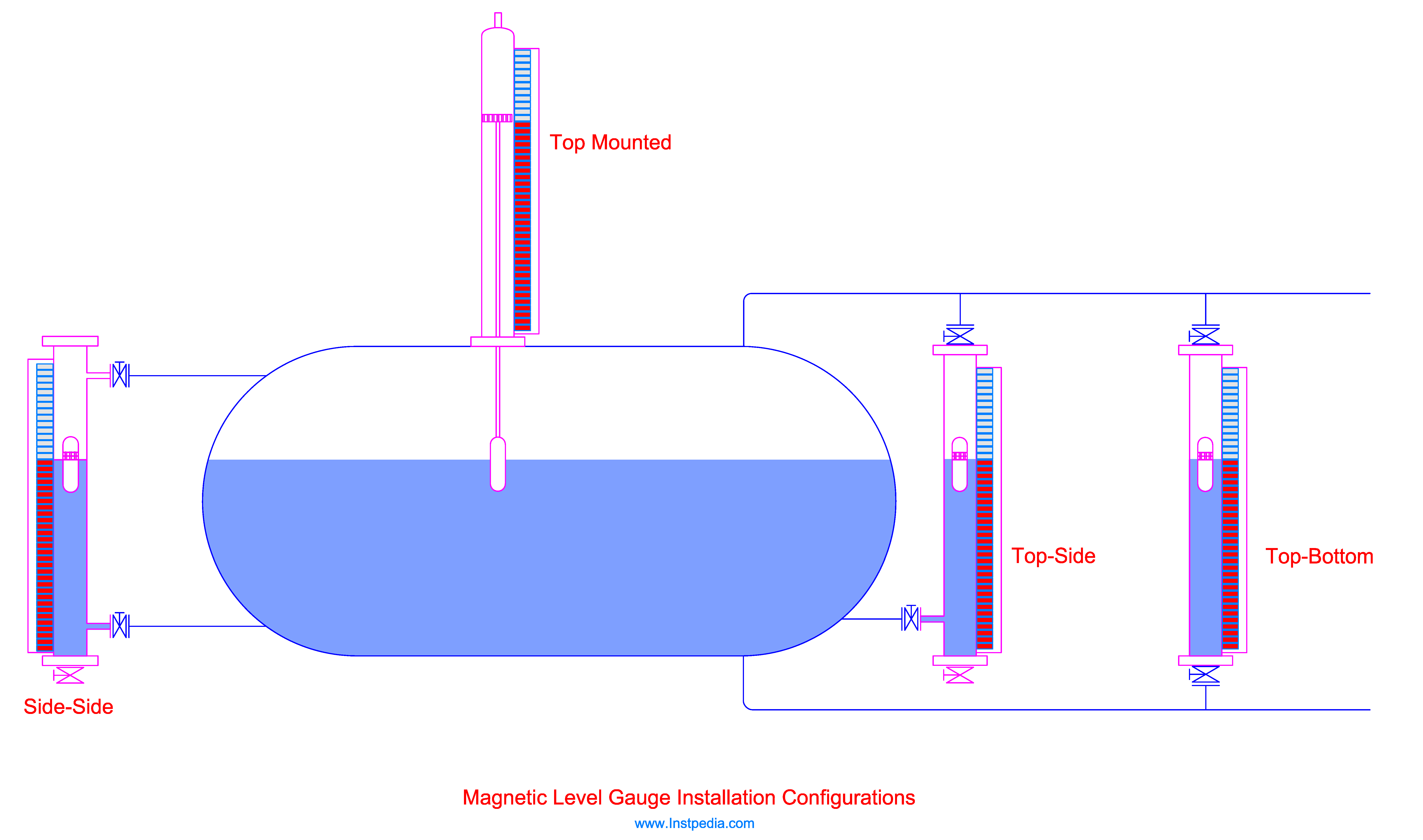
Magnetic Level Gauge Installation
Magnetic level gauge installation is mostly the same as glass level gauges installation, but magnetic level gauges could be top mounted which is not possible for glass level gauges.
Top mounting magnetic level gauge is useful for underground or covered vessels.
The most common magnetic level gauges installation configurations are; side-side, top-side, top-bottom and top mounting.
For interface level indication, float will be designed considering the lower liquid density that it sinks into the lower density liquid and remains buoyant on the heavier liquid's surface which is the interface level.
In this application more than two process connections in different levels is necessary, otherwise the interface level in the chamber and vessel may not be the same.
At least one more process connection should be considered higher than the maximum interface level.
The most important issue regarding the installation of magnetic level gauge is that it should be installed far from the equipment that affect its magnetic field.
Therefore, magnetic level gauge should be installed at least 20cm (8 in.) far from ferrous materials such as ladders, supports, carbon steel pipelines, floor grating, etc.
Location of transformers, electrical motors, magnetic separators, heat tracing cables around the vessel forming a coil or other equipment that produce electromagnetic field should be considered for magnetic level gauges installation.
Magnetic Level Gauge with Transmitter or Switch Assembly
Magnetic level gauge could be equipped with a magnetostrictive level transmitter for continuous level measurement in addition to level indication.
Magnetostrictive level transmitter consists of a wire made of magnetostrictive material which is held under tension inside a tube.
The tube is fastened to the magnetic level gauge chamber.
A current pulse produces a circular magnetic field along the wire.
Superposition of this magnetic field and the float magnetic field creates a torsional force in the wire that produces a mechanical wave in the wire proportional to the location of the float and can be converted to an electrical signal using a piezoceramic sensor.
When more accuracy is required for continuous measurement wave guided radar level transmitter could be combined with magnetic level gauge.
Radar level transmitter could be installed on top of the level gauge chamber or on another chamber connected to the level gauge chamber.
The advantages of this combination are more accuracy, more reliability, and less process connections on the vessel.
Magnetic level switches can be clamped to the indicator in order to provide discreate signals as alarms or trips at specific levels.
Switches latch into predefined position (open/close) by magnetic field of the float when it passes the switches position and unlatch by the float return.
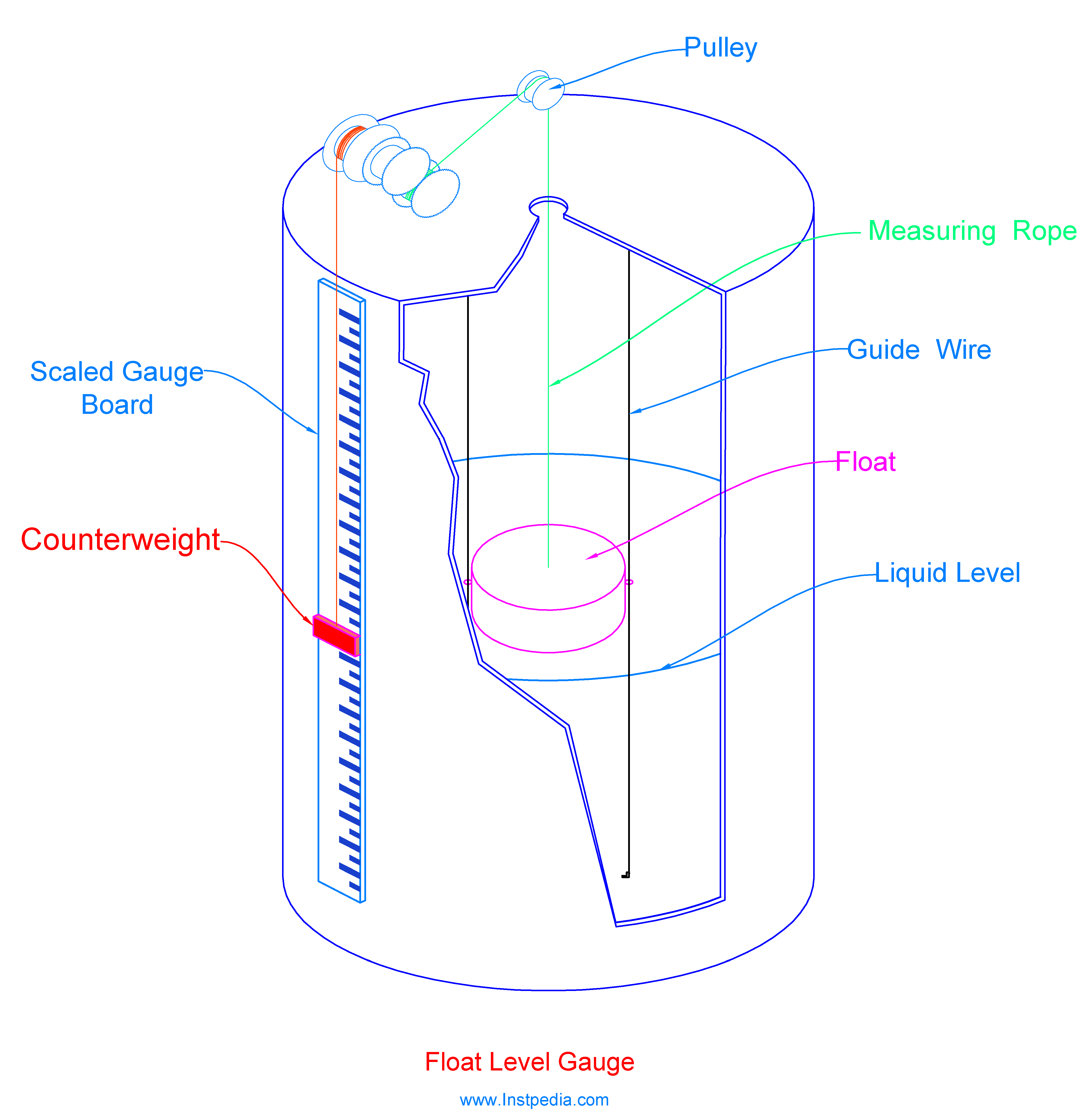
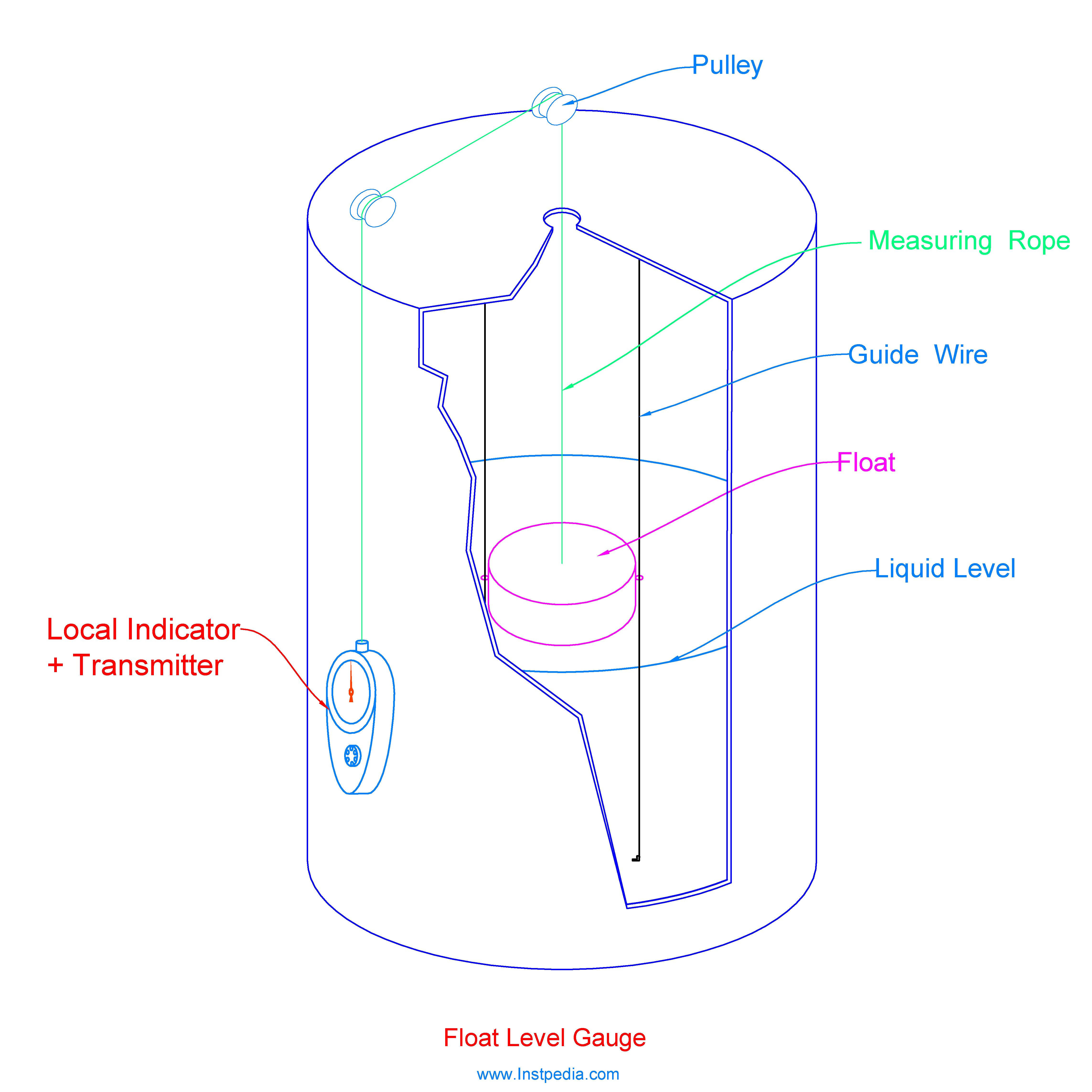
Float Level Gauge
Float Level Gauge is usually used for large storage tanks level indication.
It consists of float, counterweight, scaled gauge board, rope or chain, guide pipes and movement adjusting pullies or gears.
Float is located inside the tank which rises and falls with liquid level based on positive buoyancy.
Float is connected to a counterweight outside the tank by rope or chain through pipe guides on top of the tank.
Counterweight up and down movement in front of the scaled gauge board outside the tank is adjusted by sets of pullies or gears to keep it at the same level of the float accurately.
In some other types, adjusting pullies and gears are in a local indicator at bottom of the tank which has better accuracy and could be equipped with transmitter or switches to provide analog or digital signals for control system.
Float level gauge applications
- Large storage tanks
- Mediums with high viscosity such as liquid asphalt
- Petroleum and food products storage tanks such as Kerosene, crud oil, fuel oil and vegetable oil
- Liquid gases in spherical tanks
Float level gauge advantages
- High reliability
- Visible from distance
- Simple construction
- Low cost in comparison to other gauges for large tanks
- Low maintenance
Level Transmitter
Level transmitters are used for continuous level monitoring and control from control room.
Level transmitter output is a 4-20 mA signal in which 4 mA represents 0% level and 20 mA represents 100% level of the controlled equipment.
The most common level transmitters used in industrial applications are as the following:
- Differential pressure
- Hydrostatic
- Ultrasonic
- Radar
- Laser
- Potentiometric
- Magnetostrictive
- Displacer
- Capacitive
- Bubbler
- Float
- Servo
- Nuclear
Differential Pressure Level Transmitter
DP level transmitter is in fact a Differential Pressure transmitter which is used for measuring the level of liquid in a tank or vessel.
Differential Pressure transmitter has two pressure inlets (LP and HP) for connecting to the two measuring point pressures.
LP and HP connections are located at opposite sides of the diaphragm.
Difference between the LP and HP pressures cause the diaphragm to fold to the lower pressure side.
This movement will be sensed by sensor and transferred to an electrical output signal.
The most common pressure sensing element types for pressure transmitters are:
- Electromechanical strain gauge
- Variable Capacitance
- Piezoresistive
- Piezoelectric
Their working principle and construction are described in pressure transmitter article.
In level measurement applications the nozzle with lower elevation is connected to HP side and the nozzle with higher elevation is connected to LP side.
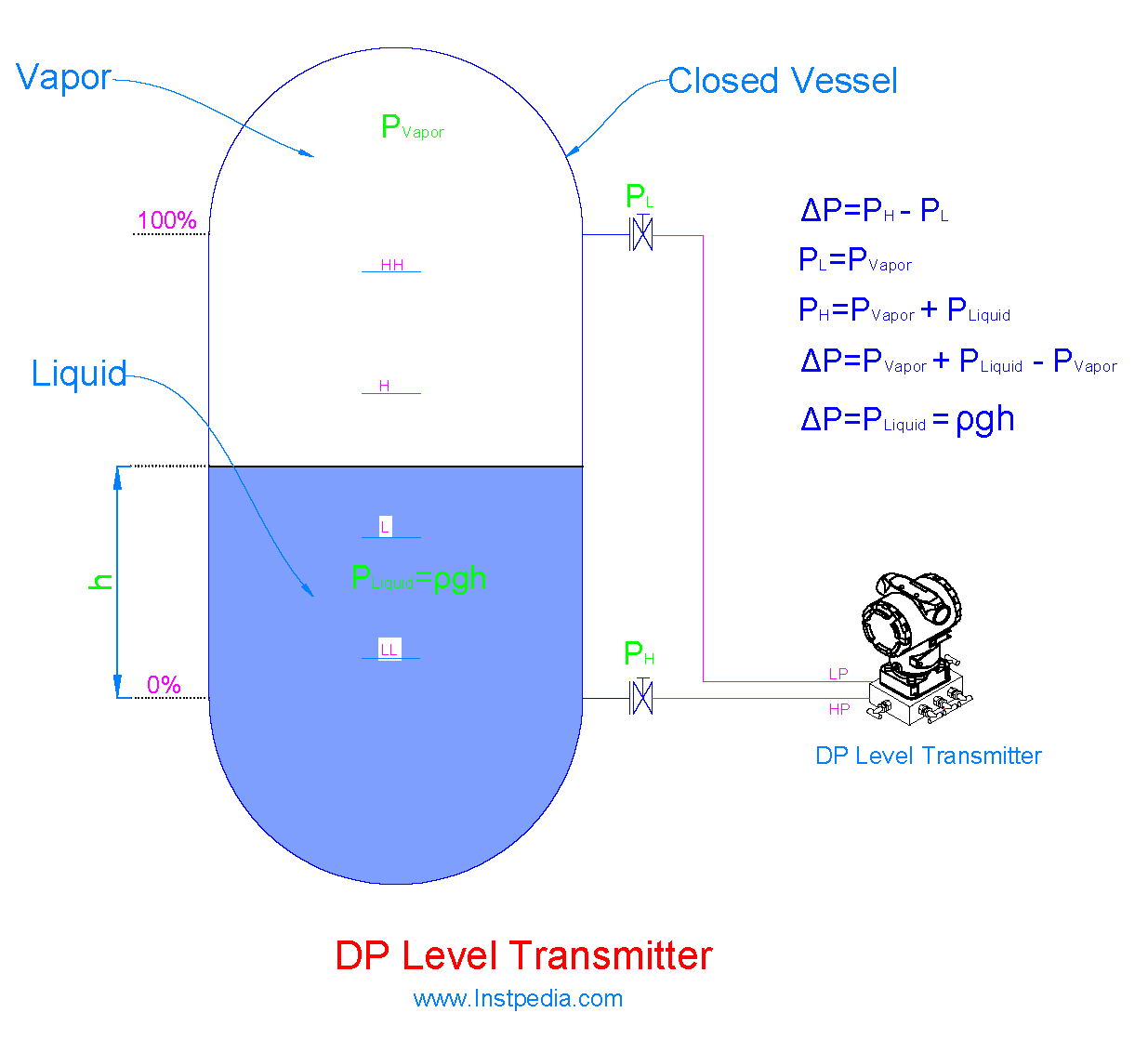
In a closed vessel, pressure of higher elevated nozzle, PL, is equivalent to vapor pressure above the liquid in the vessel, Pvapor.
Pressure of lower elevated nozzle, PH, is equivalent to liquid pressure, PLiquid, plus Pvapor.
The differential pressure measured by DP transmitter is subtraction of, PL from PH.
It means that the differential pressure is equal to liquid head pressure, ρgh.
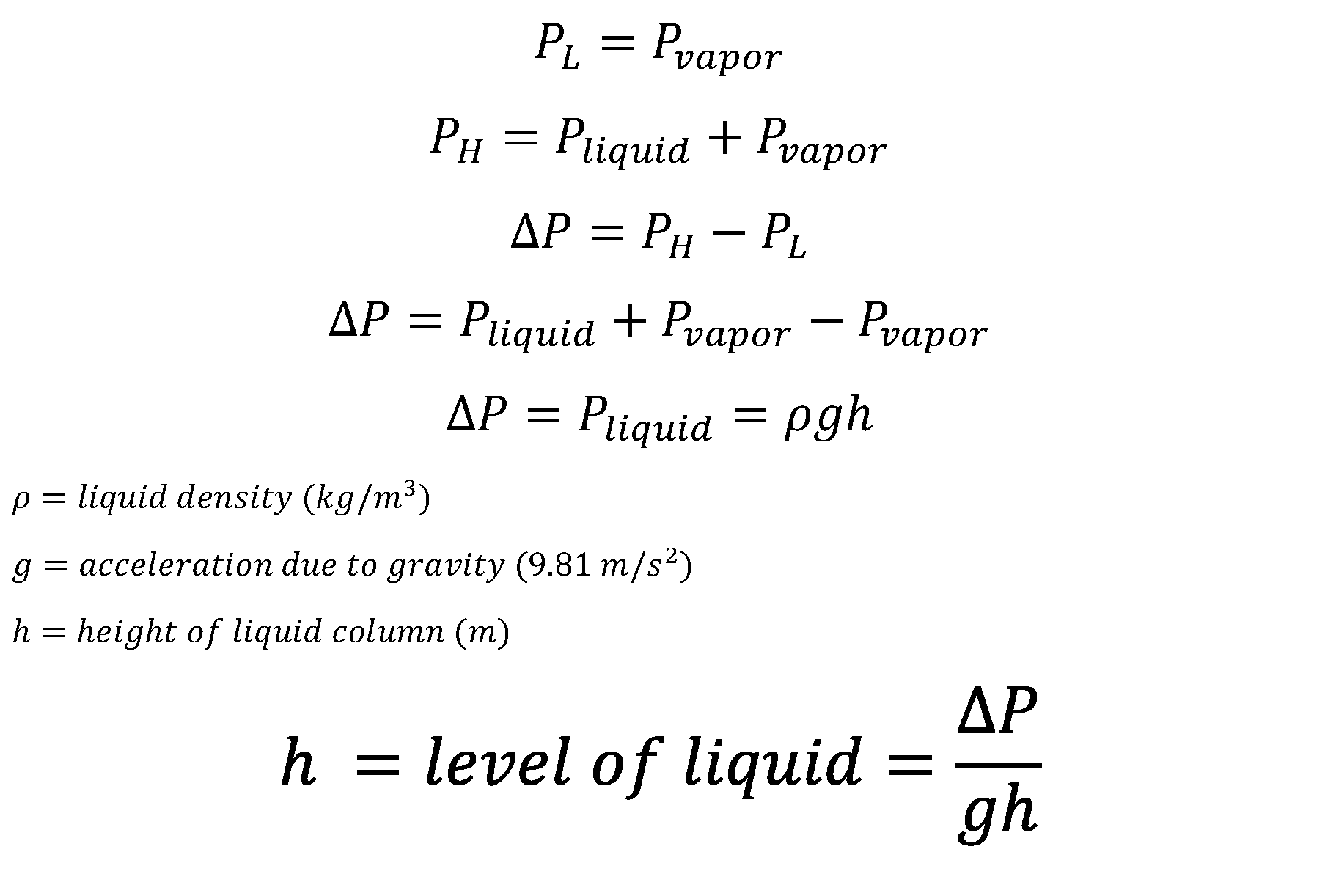
Then the level of liquid in the vessel can be derived from the above equation.
Vessel nozzles are connected to differential pressure transmitter's pressure inlets (LP and HP) by stainless steel tubes, which are called impulse lines.
If the vapor above the liquid tends to condense into liquid form, then the LP (Low Pressure) impulse line should be filled with liquid before the operation, which is called wet leg.
If the vapor does not condense into liquid form then, dry vapor of the vessel enters the LP impulse line, which it is called dry leg.
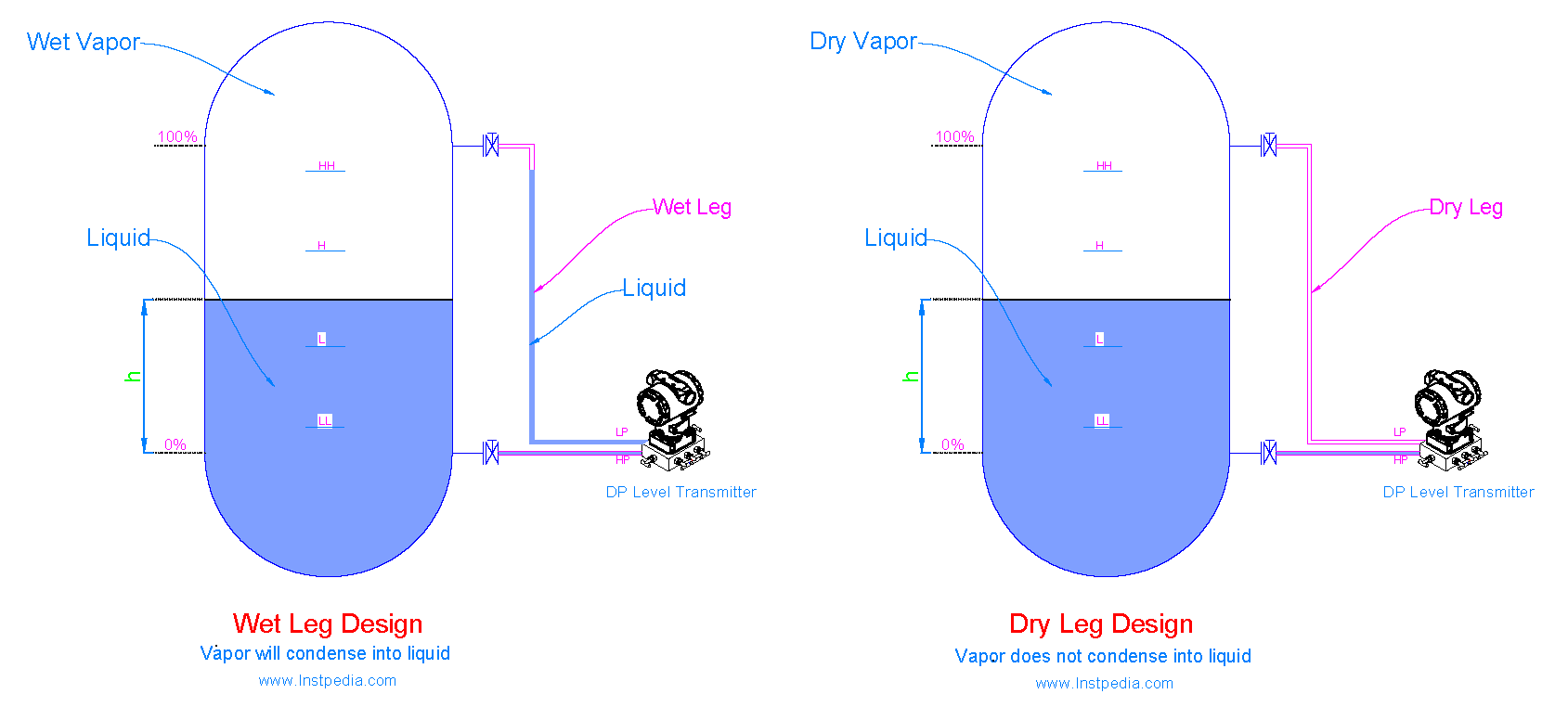
In wet led design, the sensed pressure at LP side of DP level transmitter is higher than the sensed pressure at HP side, due to head pressure of liquid in LP impulse line.
It means that the transmitter out put value for level is always a negative value.
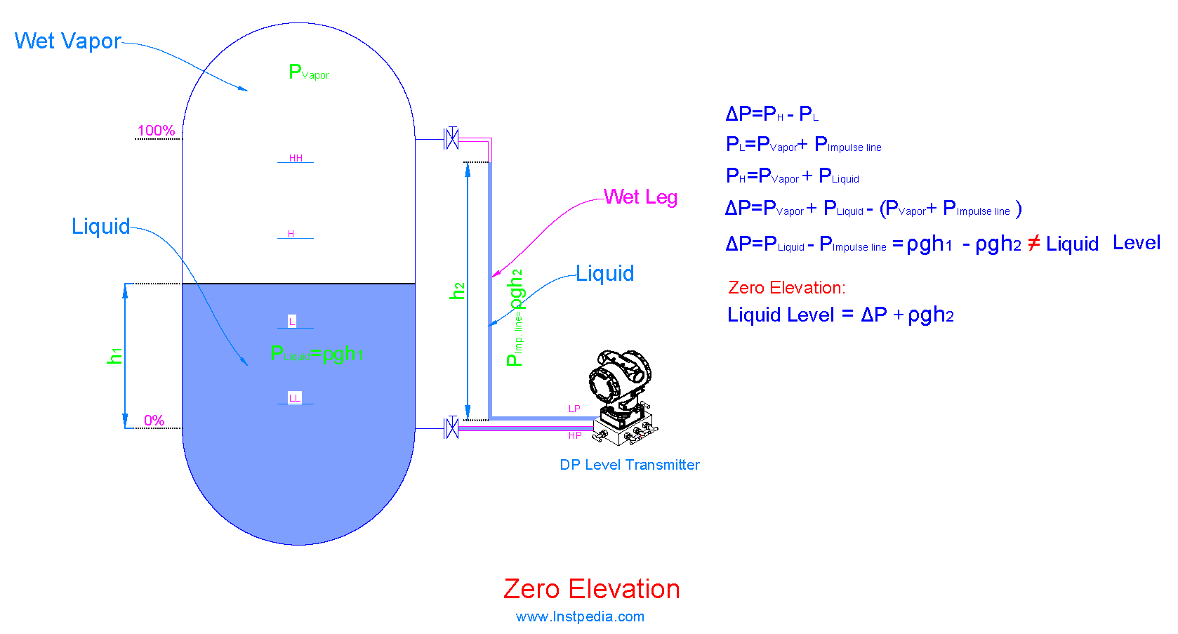
In order to solve this problem, the transmitter should be positively biased to elevate the transmitter output signal to compensate the LP impulse line head pressure.
It is called "Zero Elevation".
Most of the time, elevation of DP level transmitter is lower than the 0% level, therefore the sensed pressure at high side of DP level transmitter is higher than the required liquid head pressure because of head pressure for the remained liquid in HP impulse line.
In this situation if the vessel is fully empty the transmitter shows a value for vessel level.
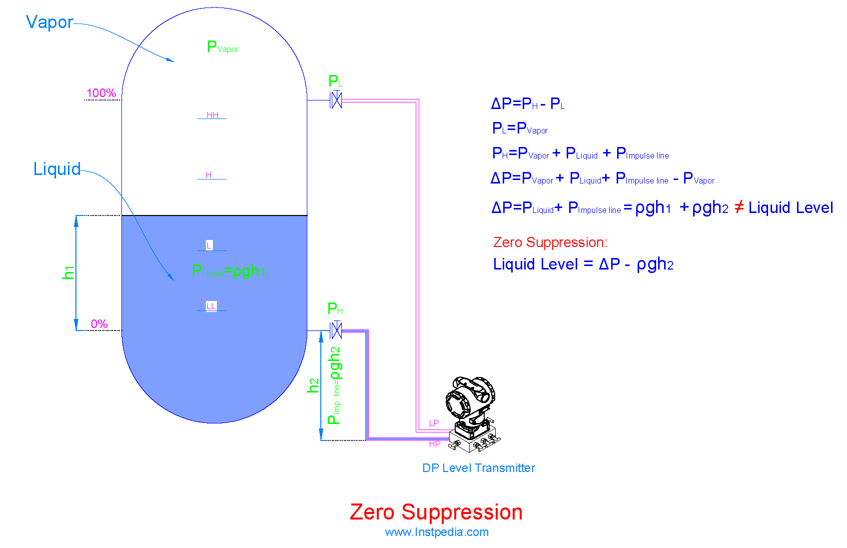
The solution is subtraction of impulse line liquid head pressure from the HP side sensed pressure which means that the transmitter is negatively biased.
It is called "Zero Suppression".
Another solution to eliminate impulse line problems is to use diaphragm seal with capillary tubes.
Diaphragm seal consists of an external sensing metal diaphragm that is connected to DP transmitter with liquid-filled capillary.
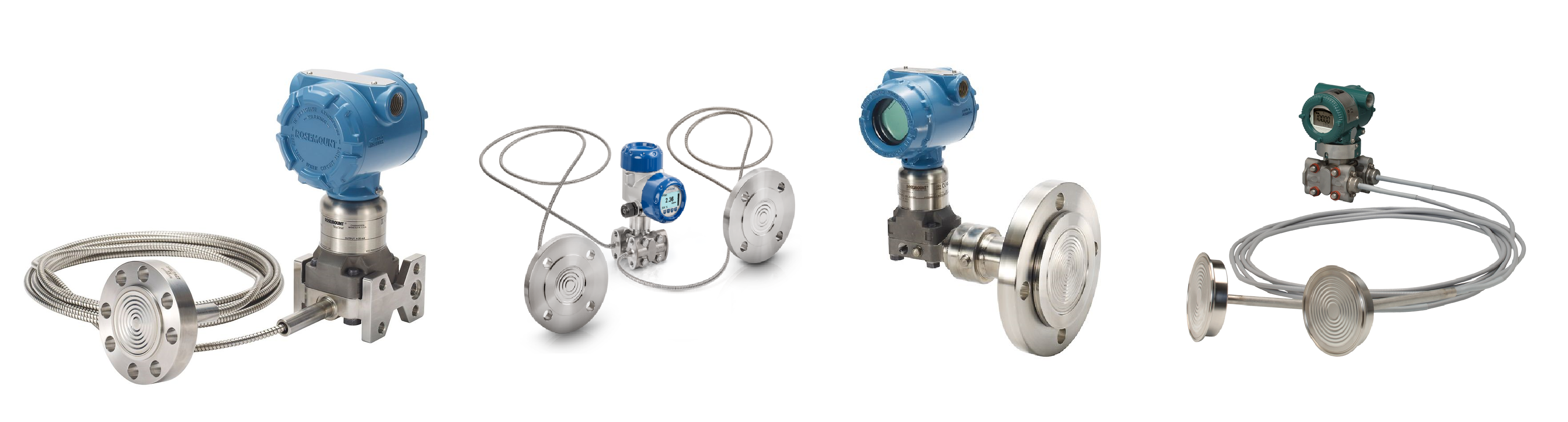
In this design, pressure sensor is isolated from the medium, and vessel pressure deflects the diaphragm membrane, therefore the measuring pressure is transferred to the filled liquid and finally to the sensor.
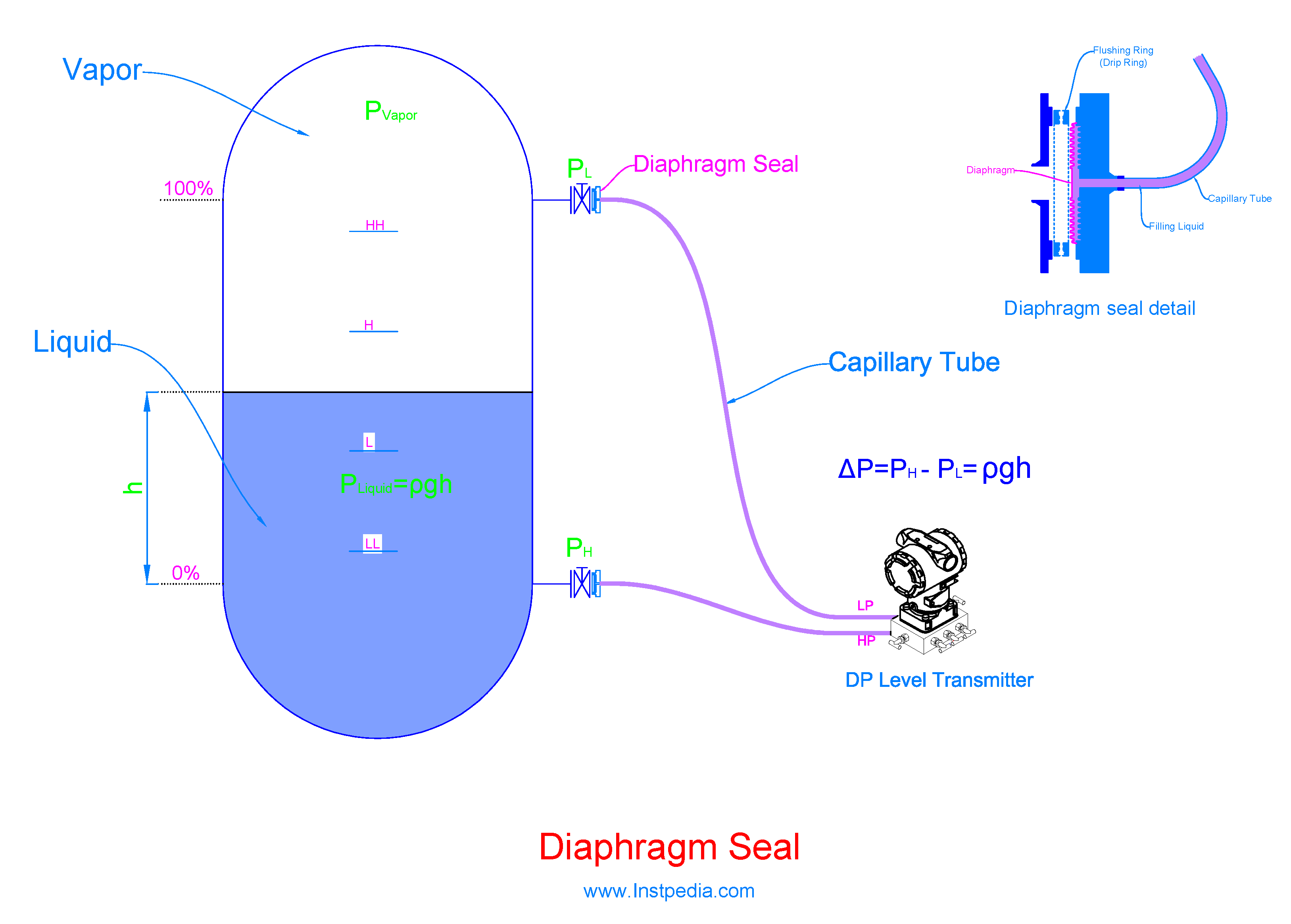
Capillary tubes are welded to diaphragm seal and transmitter by manufacturer to provide a hermetically sealed system.
Different types of diaphragm seal are described in diaphragm seal article.
It is recommended to use diaphragm seal for the following services:
- Highly corrosive services
- Leakage is dangerous and unallowed (toxic, explosive… services)
- Very high temperature services
- Cryogenic services
- Hygiene services (food and drug industries)
- Dirty services
- Services containing solid particles
- Slurry services
- Very viscous services
- Services that fluid tends to be crystallized or polymerized
Diaphragm Seal Filling Liquid
Diaphragm seal filling liquid should have low viscosity, low thermal expansion coefficient, low vapour pressure and most importantly should be stable in the operating temperature range.
At high temperature, filling liquid might be vaporized and affect the true pressure measurement.
At very low and frigid temperature, filling liquid might become very viscous or even turn into solid.
Therefore, the most important point in filling liquid selection is its stability operating temperature.
Filling liquids are available with temperature range from -90 ℃ up to 350 ℃.
Glycerin and Silicone Oil are the most common filling liquids.
In cryogenic ambient conditions Silicone Oil has better performance due to having low viscosity even in cold temperatures.
But Glycerin and Silicone Oil shall not be used for strong oxidizing agents such as Oxygen, Chlorine, Nitric Acid and Hydrogen Peroxide.
For these process fluids, Fluorinated or Chlorinated liquids such as Halocarbon or Fluorolube should be used.
Ambient Temperature Effect on Capillary
Ambient temperature changes result in expansion or contraction of capillary tube filling liquid, causing changes in internal pressure of capillary tube.
This pressure change is the measurement error of DP level transmitter with diaphragm seal and capillary system.
One solution is to consider capillary tube length of the LP side and HP side exactly the same in which the error in both sides are the same and would be eliminated automatically by ΔP calculation.
Second solution is to provide temperature sensor in DP level transmitter to compensate filling liquid density change.
The third solution is to use the contemporary DP level transmitter design, Electronic or Digital Remote Sensor.
Electronic Remote Sensor DP level transmitter
In Electronic Remote Sensor DP level transmitter design, two individual pressure sensors are used.
One installed on HP nozzle and the second one installed on LP nozzle.
The two sensors are connected to each other using a special communication cable.
One of the sensors calculate the differential pressure and converts it to 4-20ma signal.
In this new design impulse lines and capillary tubes and their problems are eliminated.
Advantages of electronic remote sensor design
- Ambient temperature affect is eliminated
- Zero Suppression or Zero Elevation are not required
- Impulse lines leakage risk eliminated
- Fast response
- Easy installation
- Low maintenance
Electronic remote sensors design is suitable for tall vessels, where there is long distance between LP and HP nozzles.
In cold climate applications, heat tracing in necessary for conventional impulse lines which in this new design will be eliminated.
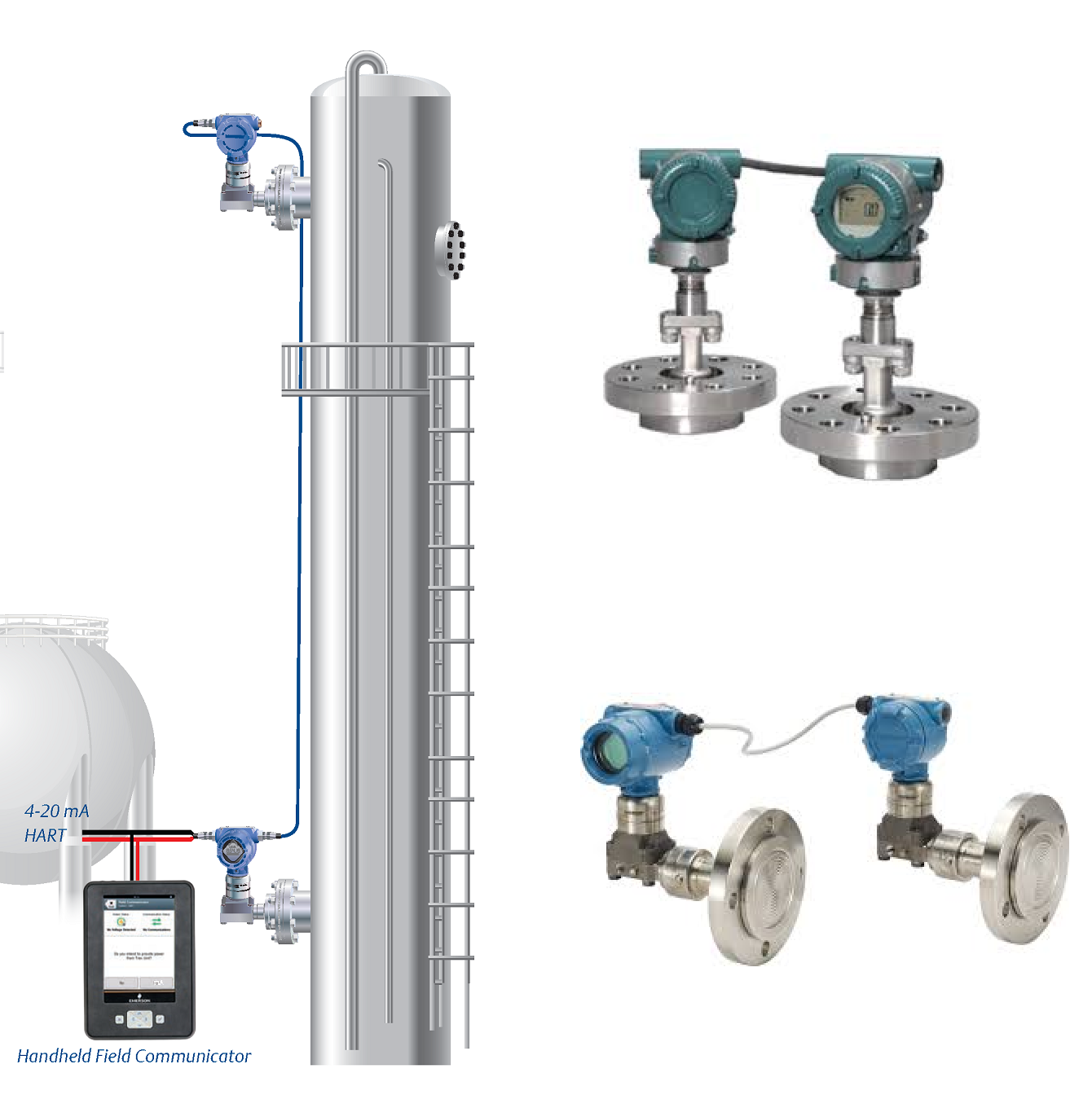
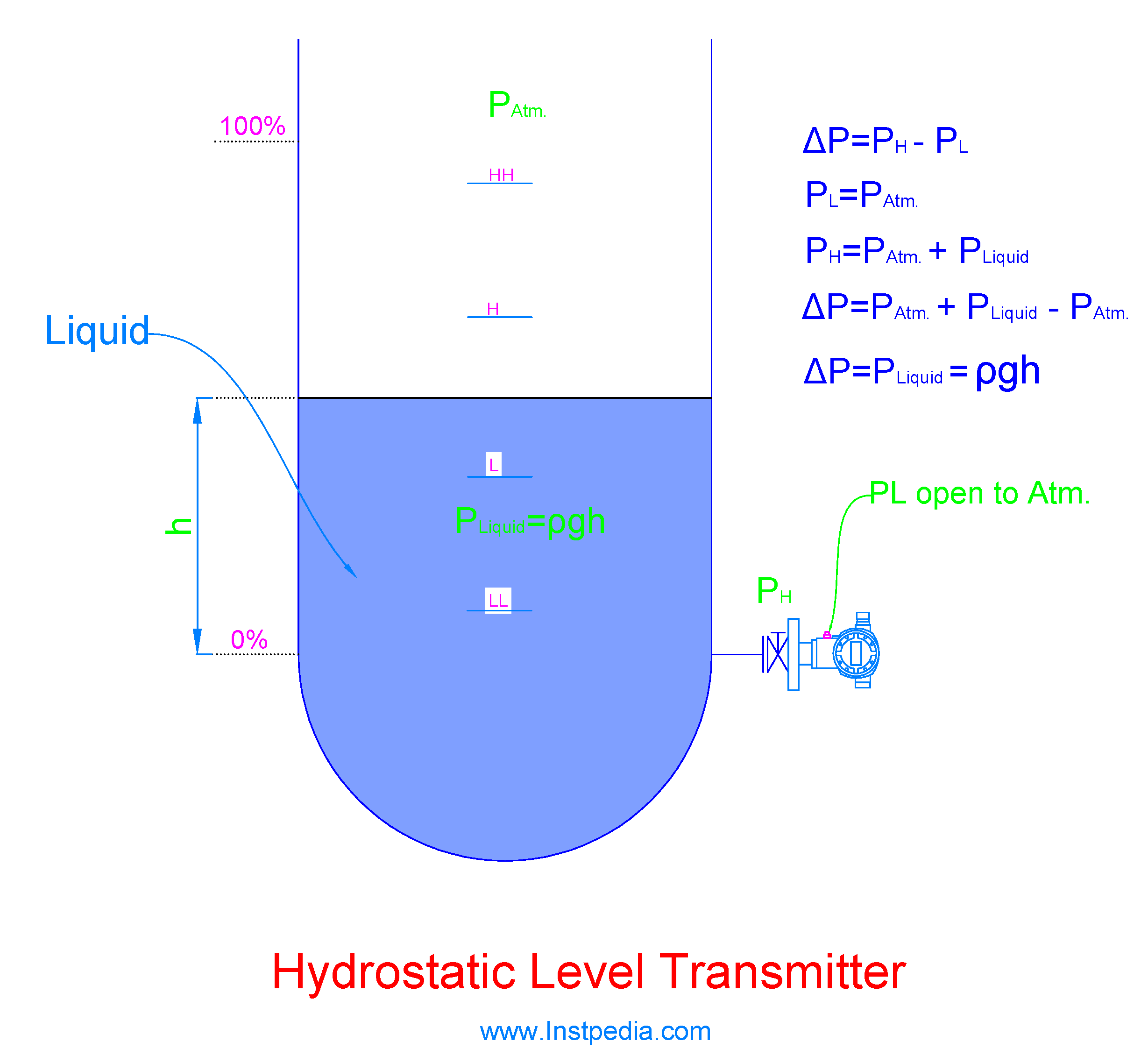
Hydrostatic Level Transmitter
Hydrostatic Level Transmitter construction is the same as DP level transmitter, but the LP (Low Pressure) side is open to the atmosphere.
Hydrostatic level transmitter is usually used for open vessels and tanks level measurement.
Submersible type of hydrostatic level transmitter is available that can be used as top mounting installation.
This type of hydrostatic level transmitter is useful for underground atmospheric tanks and sumps.
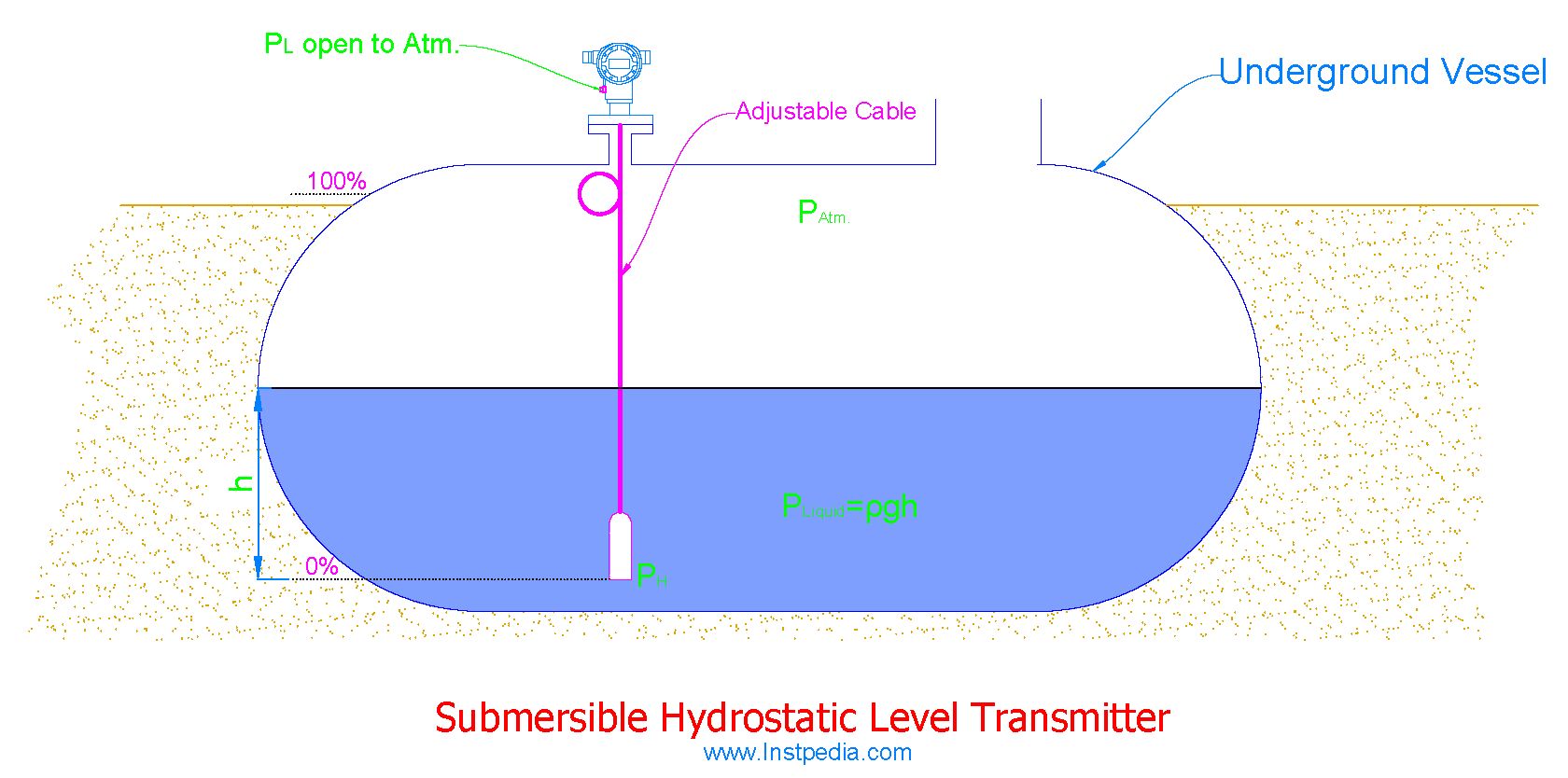
In this design sensor will be submersed in the liquid and located at 0% level point using an adjustable sensor cable or rod, and transmitter will be installed at top of the vessel.
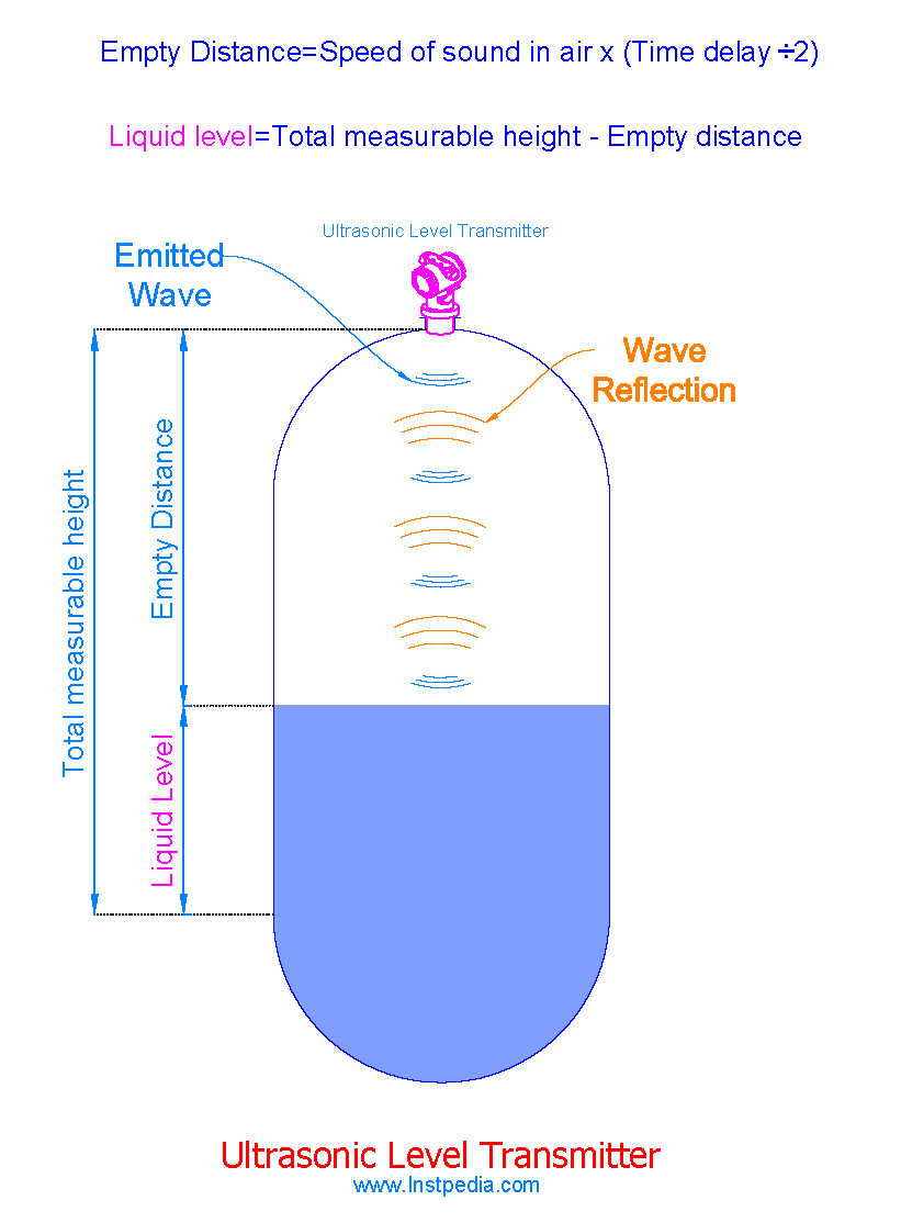
Ultrasonic Level Transmitter
Ultrasonic Level Transmitter uses ultrasound waves and operates based on Time-of-Flight principle.
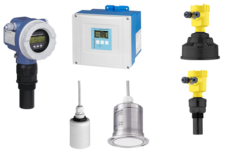
Its sensor produces an ultrasonic wave and sends it to the medium in the tank which could be liquid or solid and detects its reflection from the medium surface.
The travel time of the wave between emission to reception of its reflection which is called Time-of-Flight, is proportional to the distance between sensor and the medium surface.
Ultrasonic Level Transmitter analyzes the wave Time-of-Flight and provides the medium level in the tank as a 4-20 mA output signal.
Ultrasonic Wave Frequency Range
Sonic is the sound wave in human hearing range, 20Hz up to 20KHz.
Ultrasonic is a sound wave above human hearing range.
Some animals like bats and dolphins use ultrasonic waves between 20KHz to 200KHz and echolocation to recognize objects and food in dark.
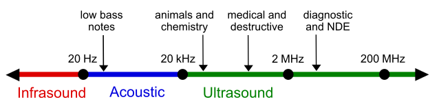
Ultrasonic waves are used for different industrial applications with frequency range of 20KHz up to 10MHz.
The ultrasonic wave frequency range used for ultrasonic level transmitters is usually within a range of 40 to 200 KHz.
Ultrasonic Level Transmitter Limitations
Temperature Variation
Sound wave speed depends on density of the medium. The higher the density, the higher the sound wave speed.
Sound travels very slowly in gasses, faster in liquids and travels with highest speed in solids
Sound speed is 343 m/s in air, 1481 m/s in water and 5120 m/s in iron.
In vessels the density of the gas above the liquid changes with temperature, therefore the speed of ultrasonic wave sent by sensor defers in different temperatures.
It causes inaccuracy in measurement for systems or ambient with fast temperature variation.
This problem could be solved with an integrated temperature sensor inside the ultrasonic level transmitter for density compensation.
In closed vessels for the best accuracy result, pressure and compressibility factor of the vapor above the liquid should be considered for density compensation.
False Echoes
The other problem of ultrasonic level transmitter refers to the construction of the vessel that could make false echo and affect the level measurement.
Thermowells, agitators, stilling wells, meshes, steam heating pipes… are obstructions in ultrasonic level transmitter point of view and produce false echoes of the submitted ultrasonic wave.
False echo problem could be solved by software modification that let the ultrasonic level transmitter to ignore undesired echoes; and it is called mapping or false echo suppression.
For mapping, the ultrasonic level transmitter will be turned on when the vessel is empty and it sends an ultrasonic wave and receives the echoes.
All the echoes from obstructions above the minimum considered liquid level will be considered as false echo and level transmitter learns to ignore them in futures.
Ultrasonic level transmitter made by some of manufacturers can do the empty vessel mapping automatically in addition to operator manual mapping.
Sensor Blockage
Ultrasonic level transmitter sensor might be blocked by dirt moving up with the medium vapor or dust.
This problem is very common in solid level measurement in hoppers or in food industry for oil level measurement.
Manufacturers have solved this problem with self-cleaning vibrator that removes dirt or dust from the sensor.
Foam on Liquid
In some applications foam accumulates on liquid surface; and echoes the ultrasonic wave back to the sensor or sometimes absorbs the wave causing false level measurement.
This problem could be solved by using a guide pipe from the sensor to the bottom of the vessel in a way that medium enters the pipe from the bottom and prevents foam accumulation on liquid surface inside the pipe.
But this solution is not 100% reliable, therefore it is recommended not to use ultrasonic level transmitter for mediums with foam, instead radar level transmitter can be helpful.
Ultrasonic Level Transmitter Advantages
- Non-contact measurement
- Simple installation and commissioning
- Loop powered (no external power supply needed)
- Low maintenance
- High accuracy and reliability
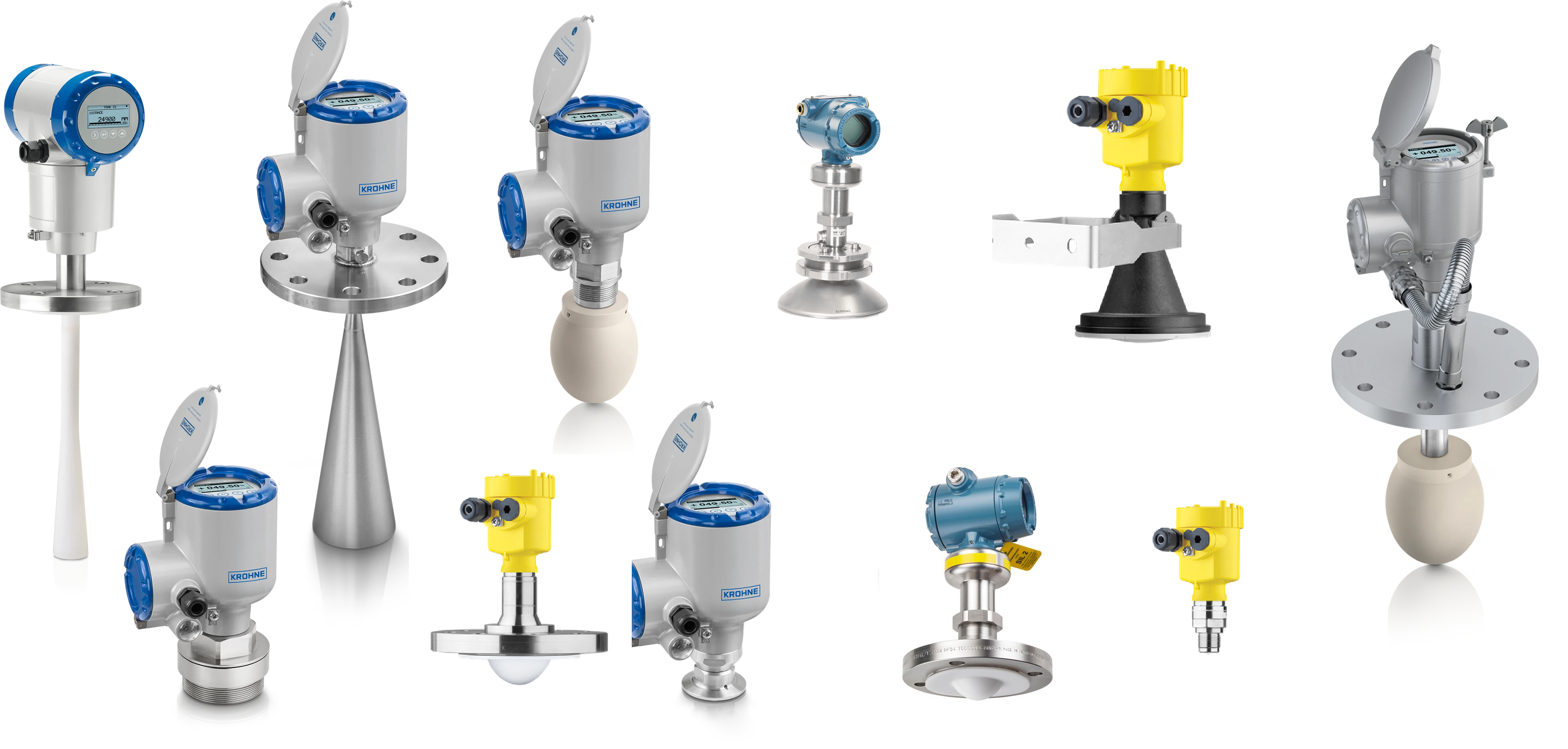
Radar Level Transmitter
There are two main types of Radar Level Transmitter:
- Contact
- Non-contact
In contact radar level transmitter, a probe or a wire is in contact with the medium in the tank or vessel, that guides the wave into the medium and its reflection from the medium surface back to the transmitter.
In non-contract radar level transmitter, there is no direct contact between the transmitter and the medium and the transmitter uses an antenna to send the radar wave and receive its reflection from the surface of the medium.
Contact Radar Level Transmitter
Contact radar level transmitter is available in two types:
- GWR (Guided Wave Radar)
- PDS (Phase Difference Sensor)
GWR is the most common used type in industry measurement.
Guided Wave Radar (GWR)
GWR level transmitter uses Time Domain Reflectometry (TDR) technology for level measurement.
GWR transmitter sends high frequency with low amplitude electromagnetic pluses through the probe or wire to the liquid and then checks the amplitude of the received reflected pulses.
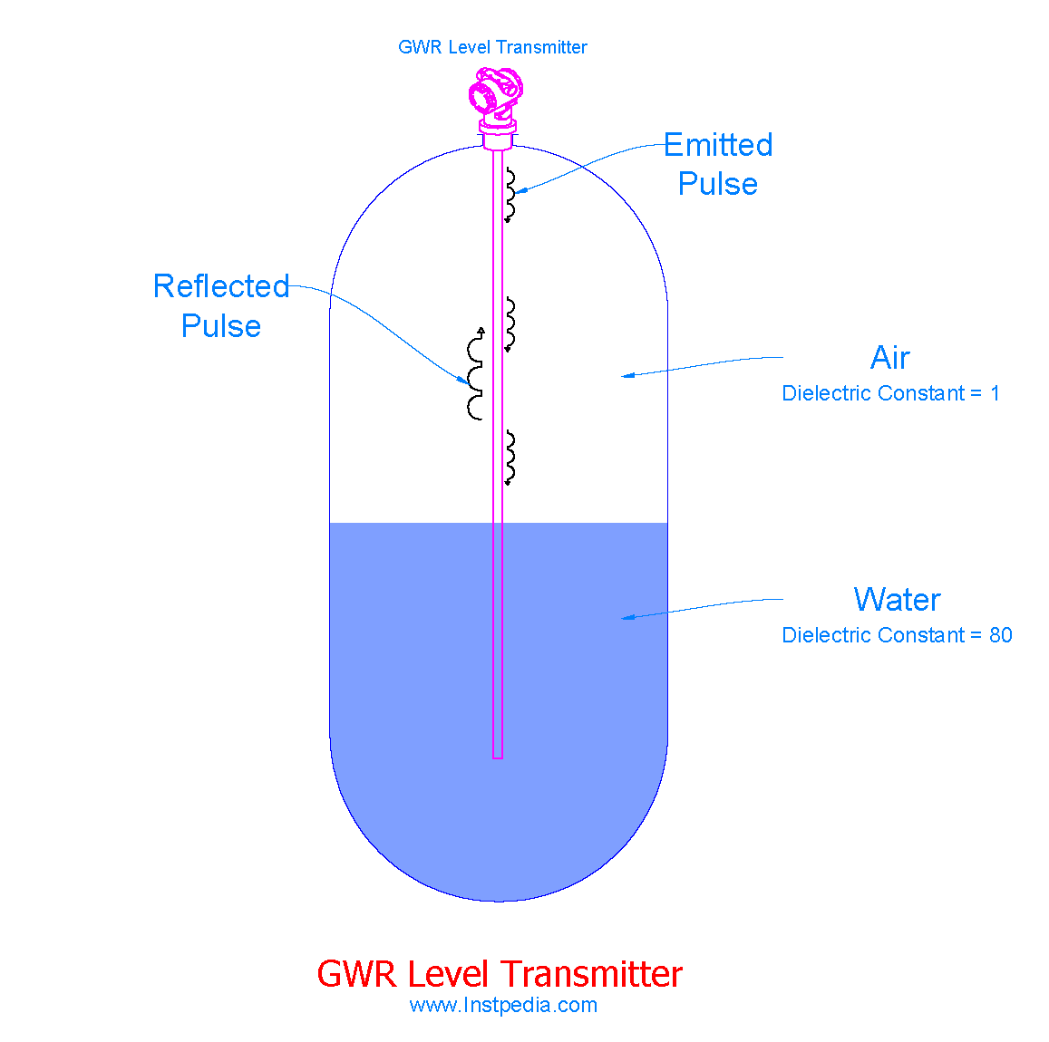
The amplitude of the reflected pulse is related to the dielectric constant of the medium that reflects the pulse.
The higher the dielectric constant, the higher the amplitude of the reflected pulse.
The waveguide impedance decreases at the point of medium surface, therefore the amplitude of the reflected pulse increases.
The transmitter receives the reflected pulse with different amplitude and recognize it as the reflection of the medium surface, then drives the level using a time scale.
If the dielectric constant of the vapour above the liquid is high (for example saturated steam vapour), it may cause delay for the reflected pulse and error for level measurement, which requires compensation or special calibration by manufacturer.
The following items should be considered for waveguide or probe material and type selection:
- Medium dielectric constant
- Temperature
- Pressure
- Medium corrosivity
- Measuring length
- Hazardous area classification
- Obstructions inside the tank/vessel
Interface Level Measurement
GWR level transmitter is a good device for interface level measurement.
For accurate interface level measurement, the dielectric difference of the upper and lower liquids should more than 6 (≥ 6) and upper liquid dielectric should be low (≤ 10).
Also, the interface should be distinct and without any emulsion layer.
Phase Difference Sensor (PDS)
PDS radar level transmitter sends a high frequency signal trough a probe. When the signal reaches the medium surface, it will be reflected but due to a sudden change in sensor impedance at the surface of medium, the frequency of the reflected signal is different from the sent signal.
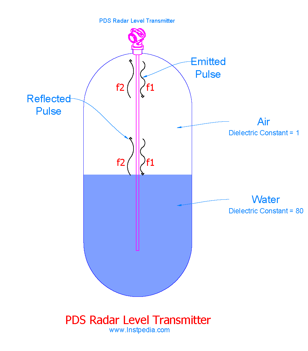
The transmitter measures the phase difference of the sent and received signals and drives the distance and finally the level of the medium in the tank or vessel.
Non-Contact Radar Level Transmitter
There are two types of non-contact radar level transmitter based on the principles of operation:
- FMCW (Frequency Modulated Carrier Wave)
- Pulse
There is no contact between the transmitter and the medium. The radar microwaves are emitted to the medium by using an antenna.
They both use time of flight technology for surface detection and level measurement.
They send the microwave to the surface of the medium and calculate the time delay of the reflected wave that guides to surface lever determination.
FMCW Radar Transmitter
FMCW transmitter sends a swept frequency signal to the medium and receives the reflected signal with different frequency.
The distance to the medium surface and then the surface level is derived from this frequency difference, using Fast Fourier Transform (FFT) or similar signal processing.
The FMCW transmitter requires more power because of its interpreting algorithm.
Formerly FMCW transmitters were available with external power only, but nowadays loop powered FMCW Radar transmitters are available in the market with acceptable accuracy.
Pulse Radar Transmitter
Pulse radar transmitter sends a pulse of microwave to the medium and receives the reflection. Then drives the level of medium surface using the transit time of the signal.
In this level measurement mediums with higher conductivity reflect a stronger signals and mediums with low conductivity absorb the wave energy and reflect a weak signal.
For low conductivity mediums FMCW radar transmitter provides more accurate level measurement in comparison to pulse radar transmitter.
Frequencies of Radar Transmitter
The microwave frequency of 5.8 GHz to 26 GHz are used by radar level transmitters.
Using waves with this range of frequency in the atmosphere is prohibited due to frequency regulations and requires license.
Metal vessels act like the Faraday cage and block electromagnetic waves, therefore using non-contact radar level transmitters for these vessels does not require license.
If the vessel is not metal, the transmitters with the frequency of 2.4GHz and 5.8GHz, which are unlicensed frequencies and allocated for Wi-Fi and other unlicensed purposes, could be used.
The most common frequencies used for radar transmitters for metal vessels are; 6 GHz, 10 GHz and 26 GHz.
Antenna
The antenna size and the frequency are related. Antenna gain will be increased by extending the size of the antenna or using higher frequency.
The antenna gain is proportional to (diameter)2 X (frequency) 2.
The beam angle for higher frequencies is smaller, hence for small nozzles high frequency radar transmitter could be used.
For example, the nozzle for 5.8GHz transmitter should not be less than 6 inches.
Antenna gain is also related to the aperture efficiency, which has effect on antenna length and shape.
There are three types of antennas:
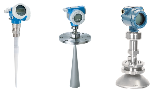
The highest gain will be achieved with parabolic antenna, while the rod antenna is the less sensitive one. Horn antenna is the most common type.
Parabolic antennas have pressure limitation, but can withstand contamination on the surface. Parabolic antennas are mostly used in tank farms.
Rod antenna is suitable for low frequency and small nozzles. Contamination degrades the rod antenna efficiency; therefore, it should not be used in submerged applications.
Horn antenna is the most recommended one. Horn antenna can have an extension to if the nozzle length is high.
Laser Level Transmitter
Laser level transmitter working principal is similar to ultrasonic and radar level transmitters, but instead of sound wave or microwave it sends a short pulse of light wave (laser) to the medium surface and receives the reflection pulse.
The transmitter calculates the distance using the elapsed time (time of flight).
The advantage of laser level transmitter to similar transmitters like, ultrasonic transmitter is that instead of beam spread, it emits a narrow direct laser pulse. Therefore, it could be used with small nozzles and false echoes are not an issue in laser level transmitter.
Laser level transmitter can be isolated from the process, by using a protection glass, which has neglectable diffusion and attenuation on laser beam.
Finally, the level is calculated from the bellow equation:
Laser Level Transmitter Applications
Laser level transmitter is suitable for the following applications:
- Solids, slurries, opaque liquids
- Moderate dusty environments (mining hoppers or bins)
- Vapor presence on liquid
- Foam-covered liquids
- Applications with several false echoes
- Vessels with several obstacles, that narrow measuring beam is required
Laser level transmitter is not proper for lever measurement of liquids with high transparency that pass through the light and provide very poor light reflection.
Safety of Laser Level Transmitter
Eye safety is a major issue in personal safety which is governed with standards of IEC and ANSI organizations for laser beam usage.
According to ANSI Z136.1, lasers of class 1, 2, and 3a are eye-safe lasers with power less than 5mw and can be use in industrial application freely without any specific protection method.
Class 3 laser is harmful for eye and should not be viewed with the naked eye.
Another important safety issue regarding the laser sensor applications is to consider the power of used laser beam in hazardous areas, with the risk of flammable gas or vapor ignition.
Laser beam may cause hot spots on the surfaces which could have the potential of explosion in hazardous areas.
Special care should be taken in use of laser level transmitters in hazardous areas and NFPA standard must be reviewed for such applications.
Magnetostrictive Level Transmitter
Magnetostrictive Level Transmitter consists of three parts:
- Electronic part (head)
- Ferromagnetic probe
- Magnetic float
Magnetostrictive Transmitter Working Principle
The electronic part in the head of transmitter produces electrical pulses down through the probe with regular intervals, that creates magnetic field through the probe.
The probe is a ferromagnetic metal wire or rod.
The float contains a magnet, the same as float in magnetic level gauges.
The float moves up and down with the surface of the liquid.
When the electric pulse reaches the float, the magnetic field of electrical pulse and the magnetic field of the float collide and produces a torsional force, that cause the vibration of the probe.
This vibration is sensed by the electronic part and it calculates the distance by measuring the time interval between sending the electric pulse and receiving the vibration pulse.
This calculated distance provides the level of the liquid surface in the vessel.
Magnetostrictive Transmitter Applications
Magnetostrictive transmitter is mostly used with magnetic level gauge in a unit assembly, that could be an economic package for level measurement. This assembly provides level local indication and continuous measurement at the same time with the minimum cost and acceptable accuracy.
Magnetostrictive transmitter is mostly used with magnetic level gauge in a unit assembly, that could be an economic package for level measurement.
In this assembly the float of level gauge is used for magnetostrictive transmitter, too. By fastening magnetic switches on the level gauge chamber, the package will be completed for level measurement and controlling process.
Local indication, continuous 4~20 mA signal and district output for trips, provide the best package for process control using level measurement.
Magnetostrictive transmitter could be used for level measurement in vessels and tanks, separately with measuring range of 10cm to 30m, with high accuracy. This transmitter is an economic solution in comparison to displacer or radar transmitters.
Magnetostrictive transmitter could be used for interface level measurement, too. In this application there would be two floats with different weight proportional to density of the upper and lower liquids.
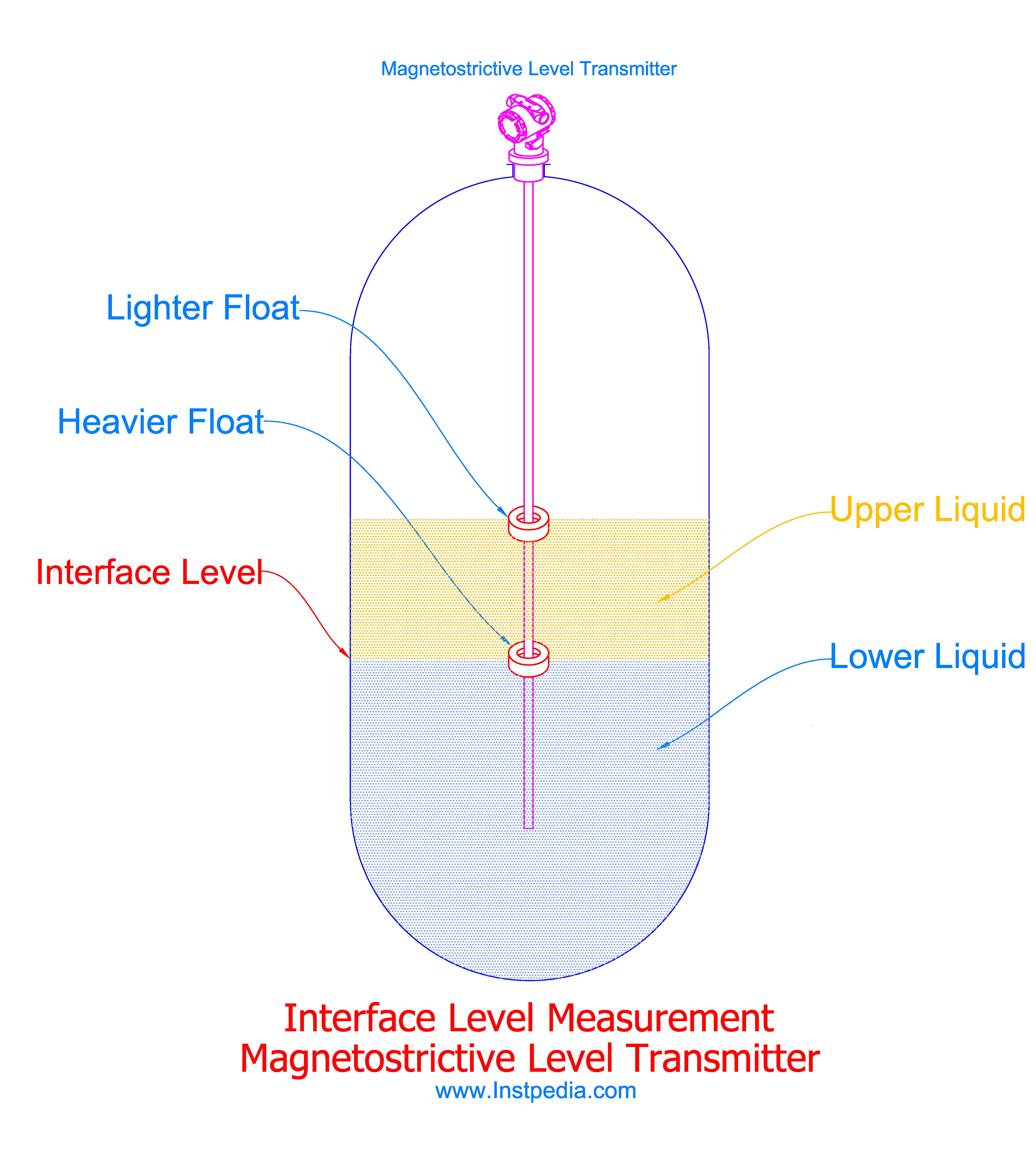
One of the floats distinguishes the interface level the other lighter float will determine the total liquid level.
One of the limitations of magnetostrictive transmitter is the process temperature, that could affect the ferromagnetic specification of the magnet in the float and also the ferromagnetic probe.
The maximum operating temperature for magnetostrictive transmitters is 260°C, however some of manufacturers have achieved a design with higher operating temperature, therefore consult the manufacturer in this regard.
The other limitation of the magnetostrictive transmitter is level measurement of viscose or dirty services, that could coat the float or stem and cause problem for easily movement of the float.
Sometimes in tank gauging systems, magnetostrictive transmitter is used as redundant level measurement besides radar level transmitter.