Pressure Measurement Instruments
Pressure Definition
Pressure is the amount of exerted force on a surface per unit area.
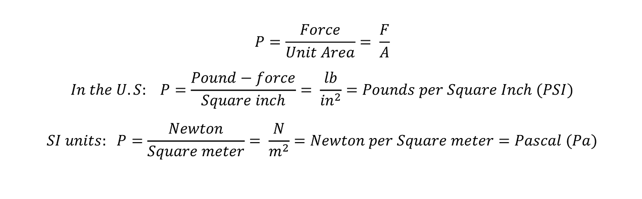
Pressure is expressed in different units, depending on the basic units of force and area.
In the U.S, the basic unit of force is Pound-force (lb) which is defined as the exerted force by one pound of a mass and basic unit of area is square inch (inch 2).
Therefore basic pressure unit in the U.S is Pounds per Square Inch (PSI).
In the countries that use metric units (SI units), the basic force unit is Newton (N) and basic area unit is square meter (m2).
Hence metric unit of pressure in these countries, is Newton per square meter, which is named, Pascal (Pa), after a French scientist, Blaise Pascal.
Other common pressure units
As mentioned before PSI and Pa are the basic pressure units, but there are several other pressure units which are used in technical documents.
The most common pressure units are; mmHG, inHG, mmH2O, inH2O and bar.
Bar is a metric unit, but is not approved by International System of Units (SI) and it is exactly equal to 100000 Pascal (100kPa).
Millimeter of mercury (mmHG) is another pressure unit, which is equivalent to the pressure of a column of mercury with 1mm height on a surface.
The inHG is the same as mmHG but equivalent to pressure of 1 inch height of mercury.
Millimeter of water (mmH2O) is defined as the pressure exerted of a 1mm height water column.
The units mmHG, inHG, mmH2O, inH2O are not SI units, which means they are not approved by International System of Units (SI).
1 bar = 100 kPa = 14.504 PSI
1 mmHG = 133.3 Pa = 0.01934 PSI
1mmH2O = 9.8 Pa = 0.001421 PSI
Pressure unit conversion table
| bar | Pa | PSI | mmHG | mmH2O | Atmospheric |
|---|---|---|---|---|---|
| 1 | 100000 | 14.504 | 750 | 10210 | 0.987 |
| 0.00001 | 1 | 0.000145 | 0.0075 | 0.102 | 0.00001 |
| 0.0689 | 6895 | 1 | 51.715 | 703.8 | 0.0681 |
| 0.001333 | 133.3 | 0.01934 | 1 | 13.61 | 0.001316 |
| 0.000098 | 9.8 | 0.001421 | 0.0735 | 1 | 0.000097 |
| 1.013 | 101325 | 14.7 | 760 | 10343 | 1 |
Gases Pressure
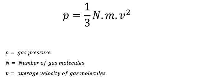
Gas molecules are in continuous random motion and they collide with each other and the container walls.
The pressure of a gas is due to collision of gas molecules with the walls of the container.
When the gas is heated, the molecules motion increases which causes the increase in collisions with the walls and gas pressure.
Gas pressure is defined as the following:
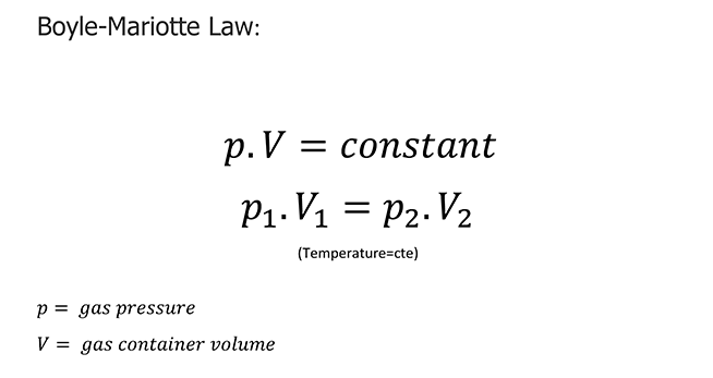
As we know gases are compressible. The relation between gas pressure and volume of gas is described by Boyle-Mariotte Law.
Boyle-Mariotte Law states that, for a fixed amount of gas at constant temperature, the volume is inversely proportional to the pressure.
It means that if you decrease the volume of gas by compressing it at a constant temperature, the gas pressure increases.
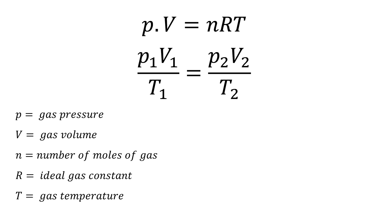
As mentioned formerly, temperature has a major role in gas pressure which can be described by Gay-Lussac's law.
Gay-Lussac's law states that for a fixed amount of gas at constant volume, the pressure is proportional to the temperature of the gas.
Combining Boyle-Mariotte and Gay-Lussac's laws, leads to ideal gas law and the following equation:
Liquids Pressure
Liquids in contrast with gases, have a very low level of compressibility that they can be assumed to be incompressible.
Liquid pressure is the exerted force by its weight and is called Hydrostatic Pressure.
It means that liquid pressure is determined by the height of liquid column and its density.
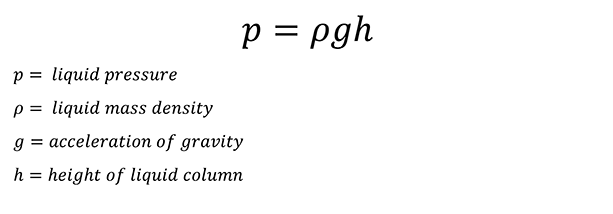
This pressure is independent of the container shape.
Just like gases, liquid pressure in a close pressurized container is distributed equally in all sides.
Pressure Types
There are three types of pressure:
- Absolute pressure
- Gauge pressure
- Differential pressure
The difference between these types is the reference point which is considered as their zero point.
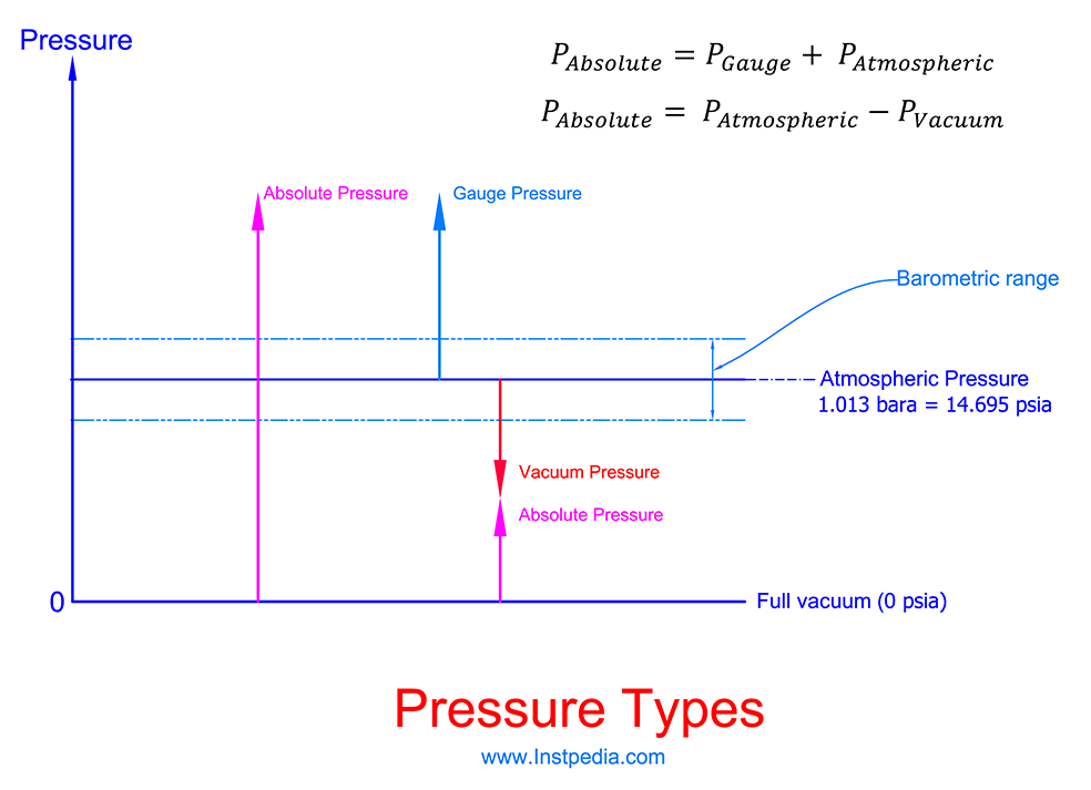
Absolute Pressure
Absolute pressure is the pressure which it's zero point is full (perfect) vacuum.
Full vacuum is the pressure of empty space in the universe.
In order to distinguish absolute pressure from other types, the letter "a" is added to the end of pressure unit.
For example: psia, bara, Pa (a) …
Full or perfect vacuum is 0 psia.
Gauge Pressure
Gauge pressure is the pressure which it's zero point is the ambient pressure.
It means that the measured gauge pressure is the pressure above atmospheric pressure.
Atmospheric pressure is the force, exerted by the earth's atmosphere.
Atmospheric pressure is also called Barometric pressure.
Atmospheric pressure at sea level is 1.013 bara = 14.695 psia and it decreases with increasing altitude.
For example, at the top of Mount Everest (the highest mountain in the world at 8848 meters) the atmospheric pressure is about 0.337 bara = 4.89 psia.
Vacuum pressure is a pressure below atmospheric pressure and its zero point is ambient in negative direction.
In another word vacuum pressure is depression of process pressure bellow atmospheric pressure.
Gauge pressure can be easily converted to absolute pressure by adding the actual atmospheric pressure to the measured gauge pressure.
In order to convert vacuum pressure to absolute pressure, we need to subtract the vacuum pressure value from actual atmospheric pressure.
Differential Pressure
The differential pressure is the difference between two independent pressures.
ΔP = P1 - P2
Other Pressure Definitions
There are other definitions of pressure, depending on the dynamic situation of the fluid.
These types of pressure are: Static pressure, Dynamic Pressure and Total Pressure (Impact Pressure).
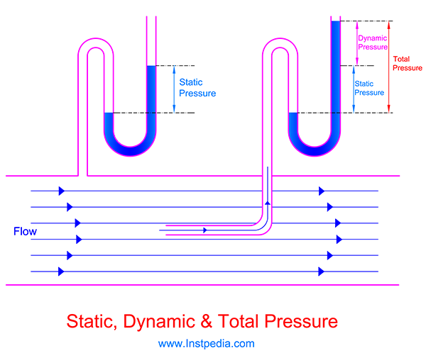
Static Pressure
Static pressure is the pressure of fluids or gases that are not in motion.
Static pressure is independent of medium's velocity and it is result of the force of gravity acting on the particles in medium which is its weight.
Static pressure sometimes is called Hydrostatic pressure.
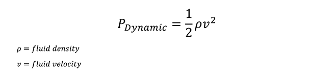
Dynamic Pressure
Dynamic pressure is the kinetic energy per unit volume of a fluid.
Dynamic pressure is a property of the fluids that are moving and it is related to the fluid's velocity.
The measured value of the pressure exerted on a surface of an object in the flowing fluid (Total Pressure) is more than the static pressure of the fluid; this overpressure is Dynamic pressure due to kinetic energy of the fluid.
Dynamic pressure is exerted perpendicular to the direction of the flow.
Dynamic pressure is defined as the following equation:
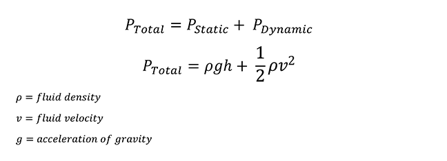
Total Pressure (Impact Pressure)
Total pressure is the pressure exerted on a surface of an object in the flowing fluid and it is sum of Static Pressure and Dynamic Pressure of the fluid.
Pressure Instrument Types
Pressure instruments which are mostly used in different industries are as the following:
- Pressure Gauge
- Differential Pressure Gauge
- Pressure Switch
- Differential Pressure Switch
- Pressure Transmitter
- Differential Pressure Transmitter
Pressure Gauge
Pressure gauge is used for local indication of pressure in industrial fields.
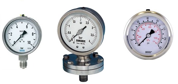
Pressure gauge consists of case, glass, dial, pointer, pressure element, moving parts, connection, etc.
There are different types of pressure gauges based on type of pressure element and measuring pressure range.
Pressure Gauge Types
The most common pressure gauges are:
- Bourdon
- Diaphragm
- Capsule
- Bellows
Bourdon pressure gauges are used for medium and high pressure ranges, but other types are used for low pressure ranges.
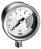
Bourdon Pressure Gauge
Bourdon Pressure Gauge is the first practical pressure gauge in different industries.
The first Bourdon pressure gauge patent was granted in 1848 to the French engineer, Bourdon, who gave his name to the invented pressure gauge.
In 1952, Edward Ashcroft purchased the Bourdon's patent.
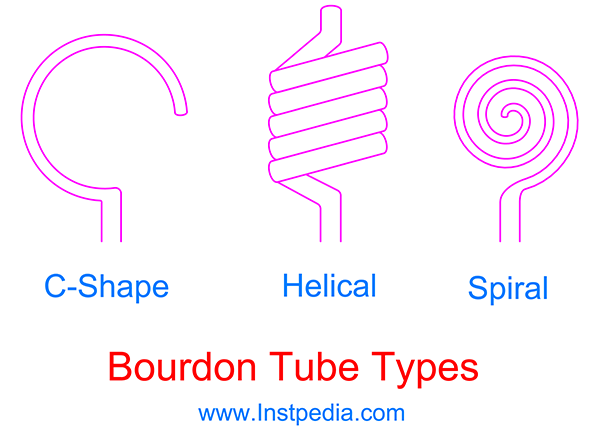
Measuring element of Bourdon Pressure Gauge is a flattened flexible metallic tube.
The end of the tube is blocked and it is formed into circular, helical or spiral shapes.
There are three types of Bourdon tubes:
- C-Shape
- Helical
- Spiral
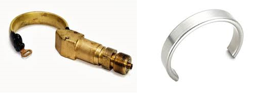
C-Shape Bourdon Pressure Gauge
The C-Shape Bourdon tube is the most common type, but for high pressure measurements helical design is used.
The radius of flattened C-Shape tube is less than a tube with the same shape but with circular cross section.
When a fluids goes inside the Bourdon tube, its pressure tends to regain the flattened tube to its previous shape which is circular cross section.
Therefore the applied pressure to the flattened C-Shape Bourdon tube cause an increase in radius of the C-Shape tube.
This change in radius results a displacement of the Bourdon tube's end.
If a pointer is connected to the end of the tube and placed on a graduated scale, then measuring the pointer displacement guides to pressure measurement.
If a pressure is high enough to bend the Bourdon tube beyond its material yield limits, it may cause the tube deformation or fracture.
Therefore Bourdon tube material has a major role in measuring range of pressure gauge.
In order to have long life expectancy, full scale range (the maximum measuring pressure on scale) is considered at displacement point of the Bourdon tube which stresses and tensions are not more than 80% of its yield limit.
It means that pressure gauge can handle the situations with pressure shocks that may exceed the full scale pressure but not more than fracture limit of the tube for a short period of time.
This limitation is called over range protection limit and it is usually 1.3 times of full scale range.
Some manufacturers has provided over range protection of 1.5 times of full scale range.
Pressure gauge range selection will be described further, with details.
C-Shape Bourdon Pressure Gauge Parts
Socket is a part that connects Bourdon tube to the process connection and guides the medium through the Bourdon tube.
Care should be taken for Socket material selection, because it is in contact with the fluid.
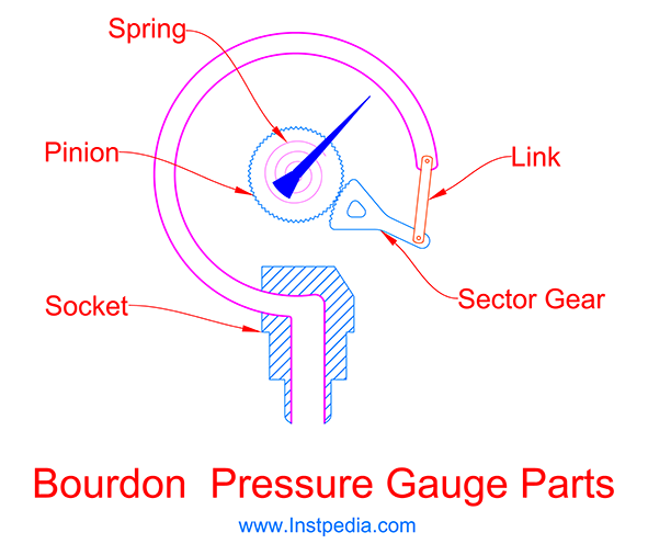
The displacement of the Bourdon tube tip is not linear and needs to be converted to the linear movement of the pointer.
Also the movement of Bourdon tube tip is not sufficient and needs mechanical amplification.
Hence there are some moving parts between tube tip and the pointer such as link, sector gear, pinion and spring.
C-Shape Bourdon Hysteresis
Hysteresis is the difference between upscaling and downscaling movements of Bourdon tube, which depends on characteristics of the Bourdon tube material.
Hysteresis cannot be eliminated, but can be minimized by heat treatment of bourdon or using bi-metal Bourdon tubes.
Helical Bourdon Pressure Gauge
Helical Bourdon tube consists of several turns similar to a coil that form a helix.
By increasing the turns or windings of the tube, pressure measuring range can be increased.
The helix form of the Helical Bourdon tube, damps the fluctuation of the process pressure that could be an advantage.
Helical Bourdon displacement is much more than C-Shape bourdon, therefore there is no need for mechanical amplification devices.
Helical Bourdon pressure gauges are more sensitive than C-shape types therefore they are used mostly in laboratory applications rather than industrial ones.
Helical Bourdon hysteresis is very low and can be negligible.
Helical Bourdon pressure gauge have high over range protection limit due to better mechanical yield limitation.
Spiral Bourdon Pressure Gauge
In Spiral Bourdon tube, the windings form a big spiral that the tube tip is located in the center of the spiral which is connected to the pointer.
Spiral Bourdon tube displacement in medium pressure range is much more than C-Shape Bourdon tube, but less than Helical Bourdon tube.
The number of spiral windings is related to the measuring pressure range.
The more windings represents larger measuring pressure range.
Due to large displacement of tube tip, there is no need for mechanical link or amplification, hence friction and inaccuracy of the moving parts will be omitted, which results better measuring accuracy.
Spiral Bourdon tube measuring range is higher than C-Shape Bourdon tube.
Therefore they are used in high pressure applications that could not be measured by C-Shape Bourdon tube.
Despite all of the advantages of Helical and Spiral Bourdon tubes, C-Shape Bourdon tubes are the most common pressure measuring element for different industrial applications.
C-Shape Bourdon tube is the first choice, in a way that in pressure gauge datasheet, "Bourdon tube pressure element" somehow means C-Shape Bourdon tube.
Diaphragm Pressure Gauge
Diaphragm Pressure Gauge invented by Bernard Schaffer, a German engineer, in 1850.
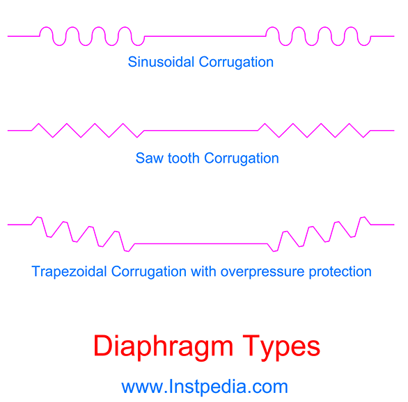
Diaphragm pressure measurement element is a flat or corrugated flexible metal disk that can be deflected by pressure of the medium.
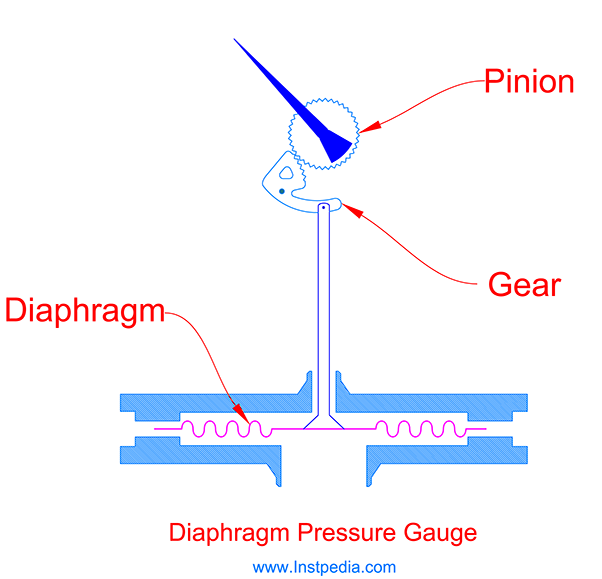
Flat diaphragm deflection is not linear, therefore by corrugating the disk, the linearity and deflection improves.
The deflection or displacement of diaphragm is related to 4th power of the diaphragm disk diameter.
It means that by increasing the diaphragm disk diameter, the greater diaphragm deflects and therefore greater accuracy is achieved.
Diaphragm thickness is important, too.
Depth of the disk corrugation is effective in linearity, and by increasing this parameter, linearity improves.
Diaphragm types
There are three types of Diaphragm pressure elements based on construction:
- Sinusoidal Corrugation
- Saw tooth Corrugation
- Trapezoidal with overpressure protection
Capsule Pressure Gauge
Capsule pressure element is basically a kind of diaphragm pressure element and consists of two diaphragms, welded together around their outer edge.
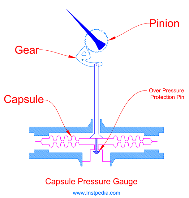
Both of the capsule diaphragms can move due to medium pressure, which doubles the displacement.
This advantage allows smaller pressures to be measured.
Hence, Capsule Pressure Gauges could be used for very low pressure gas applications.
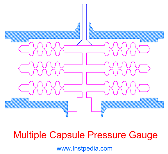
In order to increasing the displacement, several capsules can be connected in series to form a multiple capsule element for micro-pressure ranges.
Capsule pressure gauge is not suitable for liquid services, because the fluid may maintain in the capsule and cannot be drained which causes error in measurement.
Bellows Pressure Gauge
Bellows pressure element consists of thin-walled flexible metal cylindrical containers with corrugations around their outer edge connecting to each other forming an accordion shape cylinder.
When the fluid enters the bellows, its length increases which cause a large displacement.
A spring protects the bellows from deformation due to over pressure or vacuum forces.
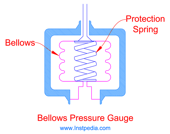
Bellows pressure element displacement is not linear, hence Bellows Pressure Gauges are seldom used in industrial applications.
Pressure Gauge Standard Ranges
The following standards have specified standard ranges for pressure gauges:
- American Standard: ASME B40.100 Pressure Gauges and Gauge Attachments
- European Standards:
- EN 837-1: Pressure gauges. Bourdon tube pressure gauges. Dimensions, metrology, requirements and testing.
- EN 837-3: Pressure gauges. Diaphragm and capsule pressure gauges. Dimensions, metrology, requirements, and testing.
As mentioned formerly in Pressure Definition topic, basic pressure unit in the U.S is Pounds per Square Inch (PSI).
Hence, pressure ranges in ASME B40.100 for pressure gauges are in PSI unit (lb/in 2.
EN 837-1 and EN 837-3, the European standards, have specified the pressure ranges in Bar or Millibar which are metric units of pressure.
According to standard EN 837-1, standard ranges for Bourdon Pressure Gauges are as the following table:
| Bourdon Pressure Gauge Ranges (EN 837-1) | Pressure Ranges (Bar) | ||
|---|---|---|---|
| 0 to 0.6 | 0 to 6 | 0 to 60 | 0 to 600 |
| 0 to 1 | 0 to 10 | 0 to 100 | 0 to 1000 |
| 0 to 1.6 | 0 to 16 | 0 to 160 | 0 to 1600 |
| 0 to 2.5 | 0 to 25 | 0 to 250 | |
| 0 to 4 | 0 to 40 | 0 to 400 | Vaccum Ranges (Bar) |
| -0.6 to 0 | -1 to 0 | Combined Vaccum & Pressure Ranges (Bar) | |
| -1 to +0.6 | -1 to +3 | -1 to +9 | -1 to +24 |
| -1 to +1.5 | -1 to +5 | -1 to +15 |
According to standard EN 837-3, standard ranges for Diaphragm Pressure Gauges are as the following table:
| Diaphragm Pressure Gauge Ranges (EN 837-3) | Pressure Ranges (Bar) | ||
|---|---|---|---|
| 0 to 0.6 | 0 to 1 | 0 to 1.6 | 0 to 2.5 |
| 0 to 4 | 0 to 6 | 0 to 10 | 0 to 16 |
| 0 to 25 | Pressure Ranges (Millibar) | ||
| 0 to 1 | 0 to 1.6 | 0 to 2.5 | 0 to 4 |
| 0 to 6 | 0 to 10 | 0 to 16 | 0 to 25 |
| 0 to 40 | 0 to 60 | 0 to 100 | 0 to 160 |
| 0 to 250 | 0 to 400 | 0 to 600 | Vaccum Ranges (Bar) |
| -0.6 to 0 | -1 to 0 | Vaccum Ranges (Millibar) | |
| -1 to 0 | -1.6 to 0 | -2.5 to 0 | -4 to 0 |
| -6 to 0 | -10 to 0 | -16 to 0 | -25 to 0 |
| -40 to 0 | -60 to 0 | -100 to 0 | -160 to 0 |
| -250 to 0 | -400 to 0 | -600 to 0 | Combined Vaccum & Pressure Ranges (Bar) |
| -1 to +0.6 | -1 to +3 | -1 to +9 | -1 to +24 |
| -1 to +1.5 | -1 to +5 | -1 to +15 |
Pressure Gauge Range Selection
Pressure Gauge range should be selected in a manner that gives the operator the correct sense of line pressure status.
It means that if the pressure is in normal operating range, the pointer should be approximately at middle of the scale or if the pressure is in maximum value, the pointer should be near the end point of the scale.
According to EN 837-2 standard, the maximum operating pressure should not exceed 75% of the maximum scale value for steady pressure or 65% of the maximum scale value for cyclic pressure.
Please note that the maximum operating pressure is not the design pressure.
Design pressure is higher than the maximum operating pressure and is the pressure which is the basis of pipe line and process equipment design.
Process line pressure may reach the design pressure, but for very short period of time and this process situation is like a transient shock.
All the equipment including pressure gauges, should tolerate the design pressure and continue safe operating after this shock.
But it does not mean that the pressure gauge scale range must cover the design pressure.
EN 837-2 standard also recommends the pressure element selection considering the pressure range as the following table:
| Pressure Element Selection (EN 837-2) | Pressure Element | Pressure Range | Reference Standard |
|---|---|---|
| Bourdon Tube | 0.6 bar to 1600 bar | EN 837-1 |
| Diaphragm | 2.5 mbar to 25 bar | EN 837-3 |
| Capsule | 1 mbar to 600 mbar | EN 837-3 |
The following procedure is recommended for selecting the best pressure scale range for pressure gauges:
-
Preliminary maximum scale value is determined by considering the maximum operating pressure as 75% of the maximum scale value.
Maximum operating pressure might not be available in datasheet, instead normal operating pressure is specified.
In this condition preliminary maximum scale value could be determined by considering normal operating pressure as 40% to 60% of maximum scale value.
-
If the preliminary maximum scale value is more than 0.6 bar, the proper pressure element is Bourdon tube and the final scale range will be selected from standard ranges specified in EN 837-1 standard.
(Please consider the standard ranges table for Bourdon pressure gauge in previous topic.)
-
If the preliminary maximum scale value is less than 0.6 bar, the proper pressure element is Diaphragm and the final scale range will be selected from standard ranges specified in EN 837-3 standard.
(Please consider the standard ranges table for Diaphragm pressure gauge in previous topic.)
-
The over range protection limit which is the maximum tolerable pressure limit bellow the element fracture is usually 1.3 times of maximum scale value.
If the process design pressure is less than the value of 1.3 x maximum scale, then pressure gauge can operate safely with the selected standard scale range.
-
If the process design pressure is more than the value of 1.3 x maximum scale, then it could damage the pressure gauge even if it happens for a very short period of time.
This problem could be solved by using an over range protection device, which can block the pressure gauge inlet when the pressure is more than the maximum tolerable limit in order to protect the pressure gauge from any damage or element fracture.
As an economical solution, if the design pressure is not far from value of 1.3 x maximum scale and if the next higher standard range covers the design pressure, then the next range could be acceptable with the condition of remaining normal operating pressure in range of 40% to 60% of maximum scale value.
Over range protection devices will be described later in pressure gauge accessories part.
Pressure Gauge Material
Case material
Plastic case is not suitable in industrial environments for pressure gauges.
AISI 316 / 316L and 304 / 304L Stainless Steels are the most proper and common materials for industrial pressure gauges case.
In areas with high density of oil & gas or petrochemical plants, the atmosphere might be polluted by corrosive gases which are not burned properly in flares and may change to a corrosive acid due to combination with ambient humidity.
In such environments AISI 316 is the best choice for case material.
Wetted parts material
Wetted parts are inclusive of the parts that are in contact with the medium such as socket, pressure element and process connection parts.
AISI 316 / 316L / 316Ti Stainless Steels could be the best and the most common material for pressure elements (Bourdon tube, diaphragm, capsule and bellows) any other wetted part material due to proper resistance against corrosive services and acceptable mechanical properties with temperature range of -254 to 816°C.
For services that contain an aggressive species such as chloride (Cl-), like seawater, Austenitic Stainless Steels (316SS, 304SS …) are not applicable.
Alloys that have PREN (Pitting Resistance Equivalent Number) greater than 40 are recommended for such services.
Monel which is a Nickle- Copper alloy or Hastelloy C which is Nickle based alloy with molybdenum content are the suitable materials for wetted parts in seawater and chloride containing services.
Moving parts material
Moving parts are not in contact with the medium, but it is necessary to be stainless steel for long life expectancy of pressure gauge.
Pointer material
Pointer material is usually from light Aluminum alloys.
Glass material
Pressure gauge glass for industrial applications should be shatterproof glass such as laminated safety glass or non-splintering plastic that will not shatter or splinter.
Caution for Acetylene
Acetylene forms explosive compounds with copper and copper alloys containing more than 70% copper.
Therefore special care should be taken for pressure gauge material selection especially for wetted parts, moving parts or even fixators in the case to minimize the risk of explosion.
For example; Brass is a copper alloy which might be very common material for process connection and wetted parts in non-industrial water or air services, but using Brass in Acetylene service is forbidden.
It is recommended that the inscription ACETYLEN to be marked on the dial for pressure gauges in Acetylene service.
Pressure Gauge Dial Size
Nominal sizes of pressure gauges dial are; 40, 50, 63, 80, 100, 150, 160 and 250 millimeters.
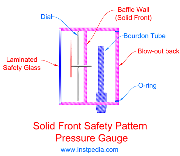
Safety Pattern Pressure Gauge
Safety pattern pressure gauges are designed to protect the operator in case of rupture of the Bourdon tube.
The operator safety is considered with the following designs:
- Safety Glass
- Blow-out device / Blow-out back
- Solid Baffle wall (Solid Front)
Safety Glass
Safety glasses such as laminated safety glasses, are superbly stronger than standard glasses.
Laminated safety glass consist of two or more glass layers with interlayers of Polyvinyl Butyral (PVB) or Ethylene-Vinyl Acetate (EVA).
The interlayers hold the glass layers in place in case of breaking.
Non-splintering plastic is acceptable according to EN 837-1.
Blow-out Device
Blow-out device is usually a plastic plug, located at the back of the pressure gauge which will blow away, when the pressure inside of the case rises.
It relieves the case overpressure and prevents the glass and case burst.
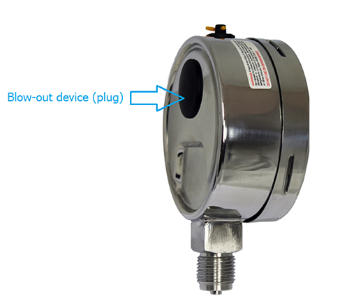
Blow-out device shall be resistant to blocking by debris and dirt and shall operate at a pressure of not more than half of the window burst pressure.
When the pressure gauge is sealed or the case is manufactured from one piece metal plate for the purpose of liquid filling, blow-out device is mandatory and shall be fitted on the gauge.
If the pressure gauge process connection is in the back of the case, the blow-out device could be fitted on top or bottom of the case.
In order to avoid blockage of blow-out device by any equipment in the field, sufficient space should be considered at the back of pressure gauge during the installation.
Blow-out Back
Blow-out back is similar to blow out device, but in this design the whole back plate of the case will blow away in the event of sudden pressure rise inside of the case.

The blow-out back shall be resistant to blocking by debris and dirt and shall operate at a pressure of not more than half of the window burst pressure and not more than 1.5 bar.
Pressure gauges with blow-out back, could be liquid filled by sealing the back plate connection to the case with o-rings.
Baffle Wall (Solid Front)
Baffle Wall (Solid Front) is a solid plate which is permanently fixed in the gauge case between bourdon tube and the dial.
If Bourdon tube fails due to a sudden over pressure, solid front protects the operator by preventing the burst of the gauge window.
The baffle wall (solid front) plate has a hole in the center for the pointer shaft which its size shall not be more than 5% of the solid front plate area.
Requirements of Safety Pattern Design
According to EN 837-1 standard safety pattern pressure gauge shall meet the following requirements:
- Energy release test
- Non-splintering material for window (Laminated glass or non-splintering plastic)
- Blow-out back
Energy release test, simulates the pressure element failure by filling the case with high pressure gas.
Safety pattern pressure gauge performance will be judged satisfactory if during the test no particles or fluids are projected to the forward direction.
Types of Safety Pattern Gauge
EN 837-1 has designated three safety codes for different levels of safety for pressure gauges as S1, S2 and S3.
- S1
- S1 is the design code for a pressure gauge with blow-out device or blow-out back.
- S2
- S2 is the design code for 40 to 80mm dial size safety pattern pressure gauge without baffle wall (non-solid front).
- In S2 design the pressure gauge meets all the mentioned three safety pattern requirements (Energy release test, non-splintering window and blow-out back).
- S3
- S3 is the design code for 40 to 250mm dial size safety pattern pressure gauge with baffle wall (solid front).
- S3 design has the highest safety level for pressure gauge.
- S3 design pressure gauge not only meets the safety pattern requirements, but also has baffle wall (solid front).
According to EN 837-1 there are two types of safety pattern pressure gauges:
- Safety pattern pressure gauge without baffle wall (S2)
- Safety pattern pressure gauge with baffle wall (solid front) (S3)
Safety Pattern Pressure Gauge Application
Projects design specification document is the first reference to determine the safety level design of a pressure gauge.
If the project specification data is not sufficient, then EN 837-2 could be a good reference in this regards.
EN 837-2 has provided the minimum safety requirement criteria for Bourdon pressure gauges as the following:
According to EN 837-2, for liquid filled pressure gauges in liquid services, blow-out device (S1 design code) is sufficient as a safety design and for dry pressure gauges on liquid services, even blow-out device is not required.
| EN 837-2 Safety level selection criteria for Bourdon pressure gauge | ||||||||
|---|---|---|---|---|---|---|---|---|
| Fluid | Liquid | |||||||
| Case filling | Dry | Liquid filled | ||||||
| Gauge size | <100 | ≥100 | <100 | ≥100 | ||||
| Pressure range (bar) | ≤25 | >25 | ≤25 | >25 | ≤25 | >25 | ≤25 | >25 |
| Min. Safety design code | 0 | 0 | 0 | 0 | S1 | S1 | S1 | S1 |
According to EN 837-2, on gas and steam services if dial size is larger than 100mm and pressure is higher than 25 bar, then pressure gauge shall be safety pattern with baffle wall (Solid front) (S3 design code).
And if dial size is smaller than 100mm and pressure is higher than 25 bar, then pressure gauge shall be safety pattern without baffle wall (S2 design code).
| EN 837-2 Safety level selection criteria for Bourdon pressure gauge | ||||||||
|---|---|---|---|---|---|---|---|---|
| Fluid | Gas or Steam | |||||||
| Case filling | Dry | Liquid filled | ||||||
| Gauge size | <100 | ≥100 | <100 | ≥100 | ||||
| Pressure range (bar) | ≤25 | >25 | ≤25 | >25 | ≤25 | >25 | ≤25 | >25 |
| Min. Safety design code | 0 | S2 | S1 | S3 | S1 | S2 | S1 | S3 |
For liquid filled pressure gauges on gas and steam services with less than 25 bar pressure, blow-out device or blow-out back shall be fitted on the pressure gauge (S1 design code).
For Diaphragm and Capsule pressure gauges due to low pressure ranges, safety pattern requirements (S2 and S3 design codes) are not applicable.
But EN 837-3 has specified blow-out device or blow-out back as a safety design (S1 design code) to protect operator by releasing the high pressure gas inside of the case, in the event of pressure element failure.
According to EN 837-3, blow-out device or blow-out back (S1 design code) is mandatory for liquid filled diaphragm and capsule pressure gauges.
And shall be resistant to blocking by debris and dirt and shall operate at a pressure of not more than half of the window burst pressure.
Liquid Filled Pressure Gauges
Pressure gauges could be filled with liquid to damp the pointer vibration in order to ease the reading.
Also the liquid filling of pressure gauges acts as a lubricant for moving parts and reduces their wear.
In regions with great ambient temperature change, liquid filling helps to avoid morning dew or frost on the gauge window.
Liquid filling avoids ingression of ambient humidity into the case, therefore protects the element and moving parts from corrosion.
Liquid filled pressure gauges are subject to build up pressure due to temperature rise, therefore hermetically sealed pressure gauges should be equipped with facilities for venting to atmosphere.
In the event of pressure element failure, inner pressure of the case increases far more quickly, hence blow-out device or blow-out back is mandatory for liquid filled pressure gauges.
The most common liquids for pressure gauges filling are Glycerin and Silicone Oil.
In cryogenic ambient conditions Silicone Oil has better performance due to having low viscosity even in cold temperatures and can protect the moving parts from freezing.
But Glycerin and Silicone Oil shall not be used for services with strong oxidizing agents such as Oxygen, Chlorine, Nitric Acid and Hydrogen Peroxide.
For these services, Fluorinated or Chlorinated liquids such as Halocarbon should be used, otherwise pressure gauge should not be liquid filed for these services.
Operating temperature shall be considered for proper filling liquid selection.
| Filling Liquid | Working Temperature Range |
|---|---|
| Glycerin | -20°C and +60°C |
| Silicone | -40°C to +60°C |
| Halocarbon | -20°C and +60°C |
OXYGEN Pressure Gauges
Oxygen in contact with hydrocarbons such as oil or grease can violently result explosion which can cause catastrophic injury to personnel and damage to properties.
Pressure gauges for Oxygen service require special design and are called Oxygen Pressure Gauge.
Halocarbon shall be used for liquid filling of Oxygen pressure gauges otherwise, it should not be liquid filled.
Oxygen pressure gauges dial markings shall include the words "OXYGE CLEAN- USE NO OIL".
Pressure Gauge Connection
Two types of connection is available for pressure gauges.
Flanged connection and threaded connection.
There are two common types of thread:
- Parallel pipe thread (G) according to ISO 228-1 Standard.
- Taper pipe thread (NPT) according to ANSI/ASME B1.20.1 Standard.
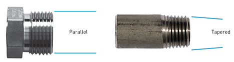
G (BSPP) thread is in accordance with British standard and NPT is in accordance with American standard.
The following thread sizes are applicable for pressure gauges relevant to the gauge size.
| Thread types and sizes for pressure gauges | Taper pipe threads | Parallel pipe threads |
|---|---|
| 1/8" NPT | 1/8" G |
| 1/4" NPT | 1/4" G |
| 1/2" NPT | 1/2" G |
The regular threaded connection size for pressure gauges with dial size of 80mm up to 160mm is 1/2" NPT.
In some documents 1/2" NPT might be specified as 1/2-14 NPT, in which the number 14, determines the threads density.
Please note that NPT threaded connections do not fit in G threaded fittings.
Therefore the thread connection type and size of the pressure gauge and 2-valve manifold must be the same.
Pressure gauge connection usually is male (1/2" NPTM or 1/2" NPT EXT) and 2-valve manifold connection is female (1/2" NPTF or 1/2" NPT INT).
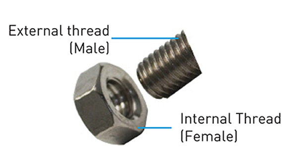
According to EN 837-1, 1/2-14 NPT EXT connection with material of Stainless steel or Monel is suitable for up to 1000bar pressure.
Flanged connection is available for pressure gauges, especially where fluid is corrosive and diaphragm seal is used.
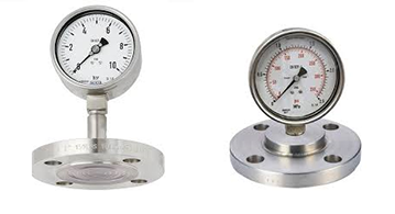
ASME B16.5 Standard has provided the details and dimension of flanges with differed material and ratings.
Flange ratings (150#, 300#, 600#…) of pressure gauge flange connection should be in accordance with the pipe class, which is described in project document, Piping Material Specification (PMS).
Pipe class defines the pipe line operating temperature, operating and design pressure and the flange rating.
Pressure Gauge Accuracy
Pressure gauge accuracy is affected by different items such as dial size, hysteresis, pointer and movement parts friction, ambient and operating temperature…
European standards, EN 837-1 and EN 837-2, define pressure gauges accuracy classes in relation with the dial size at 20 ℃ as the following:
| EN 837-1 Accuraccy Classes for Bourdon Pressure Gauges | |||||||
|---|---|---|---|---|---|---|---|
| Nominal Size | Accuracy Class | ||||||
| 0.1 | 0.25 | 0.6 | 1 | 1.6 | 2.5 | 4 | |
| 40 and 50 mm | - | - | - | - | ✓ | ✓ | ✓ |
| 63 mm | - | - | - | ✓ | ✓ | ✓ | ✓ |
| 80 mm | - | - | - | ✓ | ✓ | ✓ | ✓ |
| 100 mm | - | - | ✓ | ✓ | ✓ | ✓ | - |
| 150 and 160 mm | - | ✓ | ✓ | ✓ | ✓ | - | - |
| 250 mm | ✓ | ✓ | ✓ | ✓ | ✓ | - | - |
As the dial size increases, the better accuracy could be achieved.
| EN 837-3 Accuraccy Classes for Diaphragm & Capsule Pressure Gauges | |||||
|---|---|---|---|---|---|
| Nominal Size | Accuracy Class | ||||
| 0.6 | 1 | 1.6 | 2.5 | 4 | |
| 50 mm | - | - | ✓ | ✓ | ✓ |
| 63 mm | - | ✓ | ✓ | ✓ | ✓ |
| 80 mm | - | ✓ | ✓ | ✓ | ✓ |
| 100 mm | ✓ | ✓ | ✓ | ✓ | ✓ |
| 150 and 160 mm | ✓ | ✓ | ✓ | ✓ | ✓ |
| 250 mm | ✓ | ✓ | ✓ | - | - |
American standard, ASME B40.100, provides the accuracy classes and their permissible error in 1/4 lower, 1/4 middle and 1/4 upper of the scale in relation with dial size.
Also it has specified the maximum friction of each accuracy class.
| ASME B40.100 Accuraccy Classes for Pressure Gauges | |||||
|---|---|---|---|---|---|
| Permissible Error (∓ % of Span) (Excluding Friction) | Maximum Friction (% of Span) | Minimum Recommended Gauge Size | |||
| Accuracy Class | Lower 1/4 of Scale | Middle 1/4 of Scale | Upper 1/4 of Scale | ||
| 4A | 0.1 | Note 1 | 8.5" | ||
| 3A | 0.25 | 0.25 | 4.5" | ||
| 2A | 0.5 | 0.5 | 2.5" | ||
| 1A | 1.0 | 1.0 | 1.5" | ||
| A | 2.0 | 1.0 | 2.0 | 1.0 | 1.5" |
| B | 3.0 | 2.0 | 3.0 | 2.0 | 1.5" |
| C | 4.0 | 3.0 | 4.0 | 3.0 | 1.5" |
| D | 5.0 | 4.0 | 5.0 | 3.0 | 1.5" |
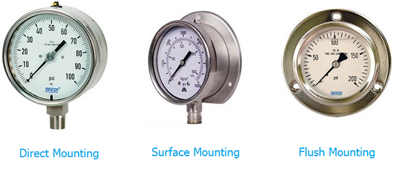
Pressure Gauge Mounting
There are three types of pressure gauge mounting:
- Direct
- Surface
- Flush
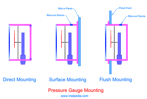
Direct mounting is the most frequently used type for pressure gauges mounting in industrial fields.
In Direct mounting, pressure gauge do not require any support and the process connection itself is sufficient for pressure gauge robust and reliable installation.
In some applications the pressure needs to be monitored a little bit far from the process nozzle, for example the pressure gauge should be located in front of a hand operated control valve to give the operator ability to monitor the pressure while throttling the control valve.
Surface and Flush mountings are proper for such remote installation, in which pressure gauge is connected to the process by using tube and fittings or capillary tube.
Flush mounting is proper for installation of the pressure gauges on control panels, in which the pressure gauge case is inside of the panel and only the window could be monitored from outside of the panel.
For Direct and Surface mountings process connection is preferred to be at bottom of the gauge.
For Flush mounting process connection is preferred to be at the back of pressure gauge in center or with an offset from the center.
Blow-out back protection, is not applicable for Surface and flush mountings instead; Blow-out device (plug), located on top or bottom of the gauge could be used.
Pressure Gauge Accessories
There are some accessories which are essential for pressure gauges installation, maintenance and protection.
The most frequently used accessories are as the following:
- Manifolds
- Syphon
- Diaphragm Seal
- Over-Pressure Protection
- Snubber
Manifold
Manifold consist of isolating valves for isolating the instruments from process line and then draining / venting them to be ready for maintenance, calibration, testing or removal.
In fact, Manifold is an isolating device in addition to piping isolating valve on the process connection.
Number of isolating valves in manifolds, is determined in relation to type of instrument.
Valve manifold and 2-valve manifold are used for pressure gauges and pressure transmitters, while 3-valve manifold and 5-valve manifold are used for differential pressure gauges and differential pressure transmitters.
The type of isolating valve in manifolds is mostly Needle valve, which is very precise and tight.
Valve Manifold (Single Valve Manifold)
In Valve Manifold, one isolating valve provides the instrument isolation and one plug is used for drain or bleed. Sometimes it is called Block and Bleed valve.
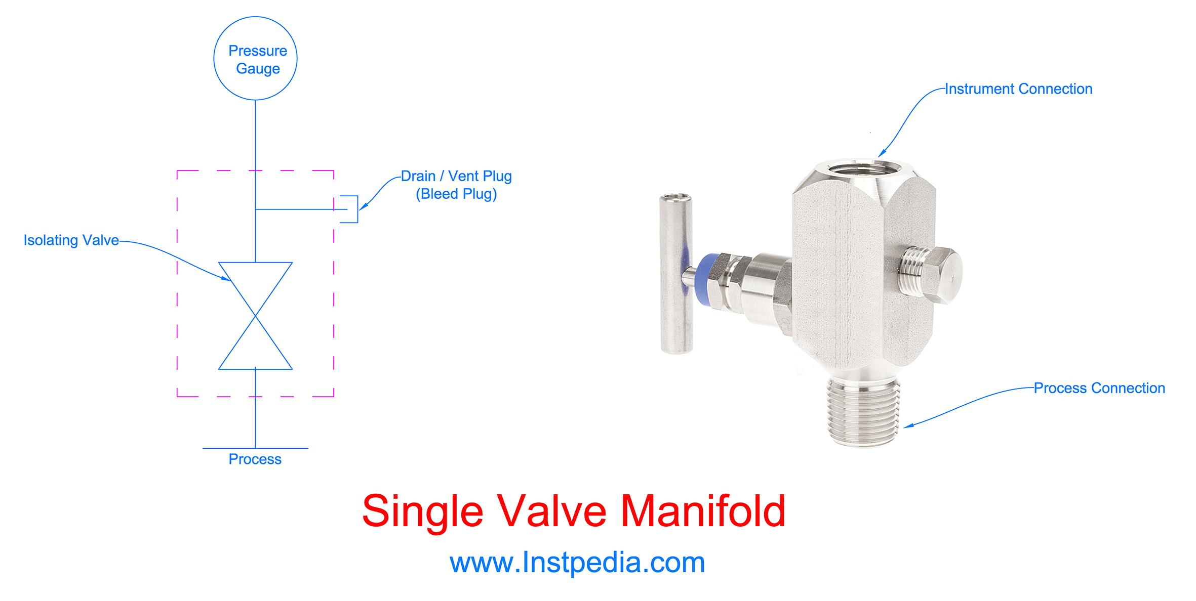
Drain / Vent plug is subject to leak due to thread damage after several times of opening and closing.
Also for high pressure applications draining or venting might be dangerous and out of control with the plug for operating personnel.
Therefore it is recommended to use 2-valve manifold for pressure gauges.
2-Valve Manifold
2-Valve Manifold has one isolating valve that provides the instrument isolation similar to Single Valve manifold, but it is equipped with another valve before the vent/drain plug.
This design is more reliable and safer for operating personnel.
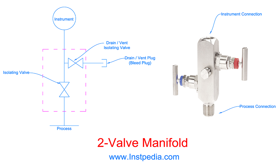
For corrosive, toxic or dangerous services, the vent/drain hole could be guided to a safe area or closed drain/vent system by using tube and fittings for a higher safety level.
2-Valve manifold is called block and bleed valve, too.
Double Block and Bleed Manifold
Double Block and Bleed Manifold is applicable for fugitive services which two isolating valve is required in order to avoid fugitive or toxic fluid emission.
Globe style needle valves or ball valves could be used as isolating valves due to their high shut off class and reliability is this manifold.
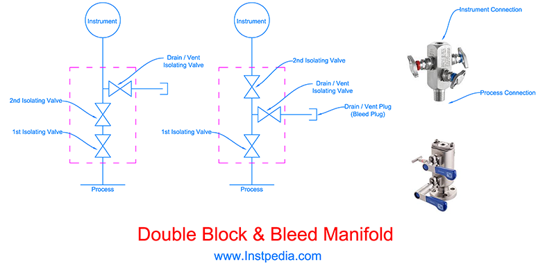
When there is no sufficient space for both piping isolating valve and manifold, using the compact Double Block & Bleed Manifold could be a good solution.
Mono-Flange Manifold
Mono-flange design manifold is suitable for applications where instrument and process connections should be flanged.
Also the compact design reduces the occupied space from nozzle to instrument.
Mono-Flange design is proper for high pressure, fugitive or toxic services.
Mono-flange manifold could be designed as block & bleed valve or double block & bleed valve.
3-Valve Manifold
3-Valve Manifold has two isolating valves for LP and HP sides that provides the instrument isolation from the process line.
There is an Equalize valve between LP and HP sides, which is closed during operation.
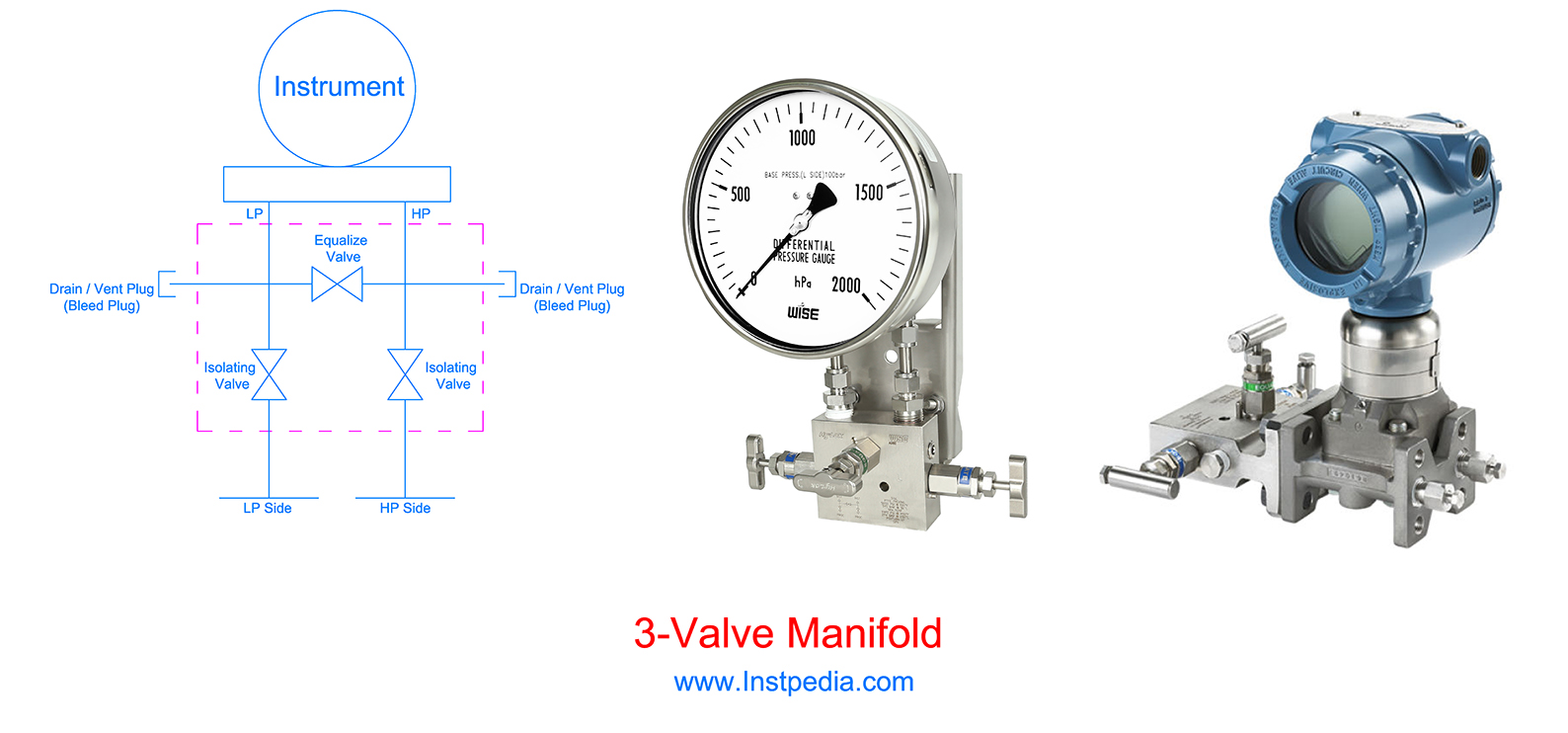
Equalize valve is used for calibration and zero check.
When the equalize valve is open, the pressure of both sides are the same, hence the differential pressure gauge should indicate zero.
Two plugs will be used for Vent/Drain of pressure sides.
5-Valve Manifold
Similar to 3-Valve manifold, 5-Valve manifold has two isolating valves for LP and HP sides that provides the instrument isolation from the process line.
It has two valves for both LP and HP sides drain / vent during maintenance which make 5-Valve manifold a safer design for operator personnel in comparison to 3-Valve manifold.
There is an Equalize valve between LP and HP sides, which is closed during operation.
Equalize valve is used for calibration and zero check.
When the equalize valve is open, the pressure of both sides are the same, hence the differential pressure gauge should indicate zero.
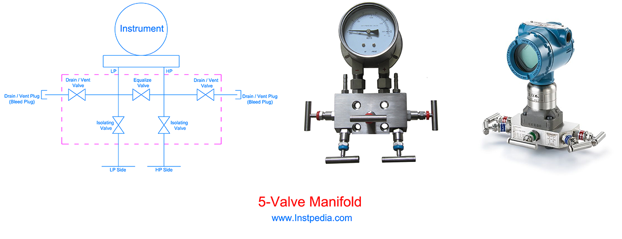
For corrosive, toxic or dangerous services, the vent/drain holes could be guided to a safe area or closed drain system by using tube and fittings for a higher safety level.
Syphon
Operating temperature has an effect on measurement accuracy therefore gauge should be protected from high operating temperature.
For liquid filled pressure gauges, the operating temperature range of filling liquid should be considered for proper operation of the gauge.
Syphon is a temperature protection accessory for pressure gauges.
For high temperature services especially steam services, syphon should be installed between instrument and the process tapping, to reduce the temperature of medium before entering the pressure element.
There are three types of syphon:
- U-shape
- Pigtail
- Coil
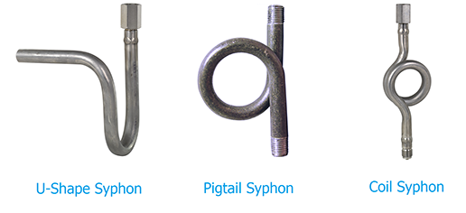
U-shape syphon is used for horizontal pressure tapping applications.
Pigtail syphon is used primarily for vertical installation.
Coil syphon is used primarily for horizontal installation.
These syphons are designed in way to let accumulation of condensate in the syphon to prevent direct contact of hot medium with the pressure element.
For this reason it is recommended to fill the syphons with condensate before commissioning.
Another advantage of using syphon in steam services is that the syphon shape and its turns protects the pressure element from pressure surges or water hammer.
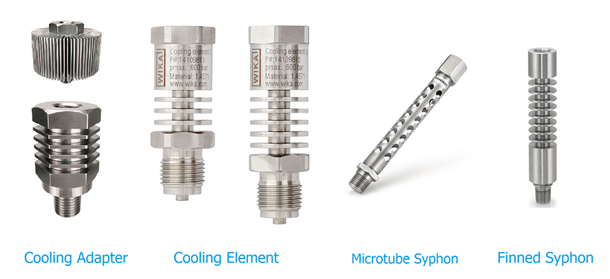
Temperature reducing of syphon is based on convection heat transfer principle.
Syphon increases the contact area of air and the tube by increasing the tube length.
Using this principle there are some other innovative designs for syphons to reduce the temperature such as; finned syphon, micro tube syphon, cooling adapters or elements etc.
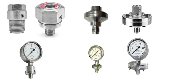
Diaphragm Seal
In some applications, in order to protect the pressure element, it should not be in direct contact with the medium.
As a solution a metal diaphragm will be installed on the process connection and the space between the diaphragm and pressure element will be filled with an especial liquid.
Therefore the pressure element is isolated from the medium and the line pressure is transferred by diaphragm to the filled liquid and finally to the element.
It is recommended to use diaphragm seal for the following services:
- Highly corrosive services
- Leakage is prohibited (toxic, explosive,… services)
- Very high temperature services
- Cryogenic services
- Hygiene services (food and drug industries)
- Dirty services
- Services containing solid particles
- Slurry services
- Very viscous services
- Services that fluid tends to be crystallized or polymerized
- Remote installation is required
There are two types of diaphragm seal; threaded and flanged.
Threaded Diaphragm Seal
Threaded diaphragm seals are normally used for low pressure corrosive services.
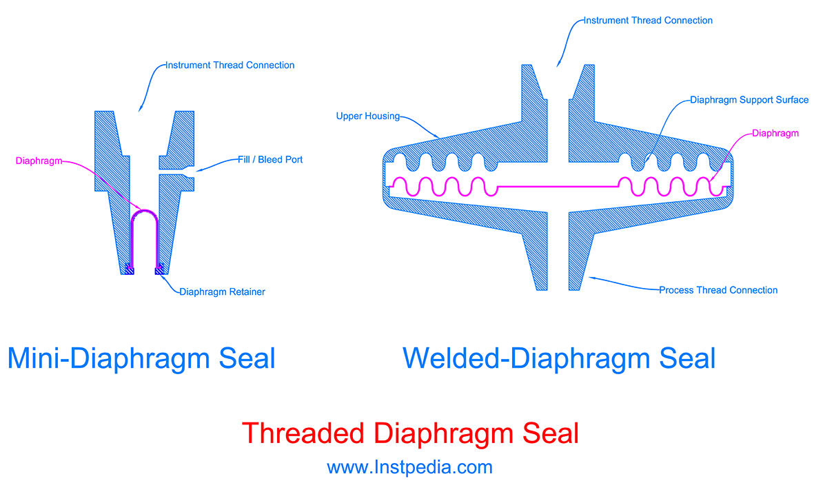
There are some compact designs that are called mini-diaphragm seals.
Threaded diaphragm seal are the best economic solution for low pressure corrosive services.
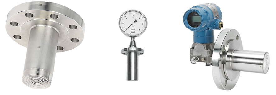
Flanged Diaphragm Seal
Flanged Diaphragm seals are used for high pressure services where the process connection is flanged.
The most common types of flanged diaphragm seal are:
- General design
- Extended design
- Pancake (Wafer) design
- In-Line design
General Design Flanged Diaphragm Seal
In general design flanged diaphragm seal, diaphragm is welded to the upper housing which has flange connection and will be bolted to the process connection flange.
The outlet part of diaphragm seal is connected to the instrument or in case of remote installation is connected to capillary tube.
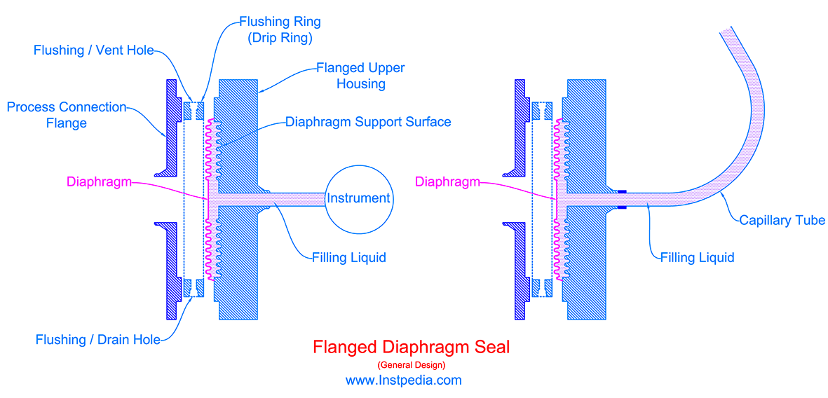
All the space between diaphragm and instrument should be filled with an especial filling liquid.
Therefore using manifold with diaphragm seal is not applicable, because the filled section is sealed and there is not requirement for vent or drain.
But for non-toxic or non-explosive services a flushing ring (drip ring) with two thread connections for vent and drain, will be installed between the diaphragm sea and the process connection flange.
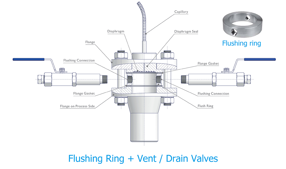
Flushing ring (drip ring) gives the operating personnel the ability to flush and clean the diaphragm seal with water or vent/drain the medium between piping isolating valve and the diaphragm seal before removing the diaphragm seal during maintenance.
Vent / Drain holes on flushing ring could be equipped by isolating valves using a long nipple.
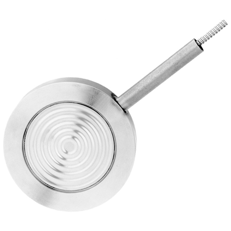
Extended Diaphragm Seal
Extended Diaphragm Seal is used in services that nozzle clogging risk is high, such as high viscosity, slurry, dirty, polymerizing or crystalizing services.
In this design the upper housing of the diaphragm seal is extended through the nozzle and the diaphragm is at level of the pipe or vessel wall.
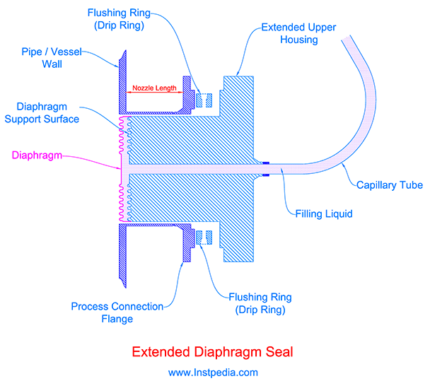
Extended Diaphragm Seal does not let the fluid enter the nozzle and cause the clogging or blocking the nozzle and interfere the pressure measurement.
Flushing ring can be used for flushing and washing the nozzle and diaphragm seal.
Pancake (Wafer) Diaphragm Seal
In Pancake (Wafer) diaphragm seal design, diaphragm seal will be clamped between process connection flange and a blind flange.
The instrument or capillary tube connection in this design, is from the side.
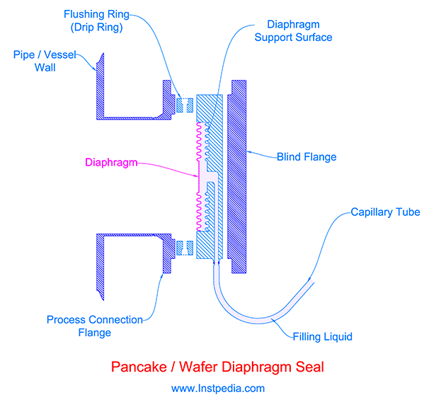
One of the advantages of Pancake (Wafer) diaphragm seal is that the same diaphragm seal could be used with flanged process connections with different ratings.
Pancake (Wafer) diaphragm seal is known as Sandwich or Cell-type diaphragm seal, too.
In-Line Diaphragm Seal
In this design the diaphragm seal is installed directly in the process flow line.
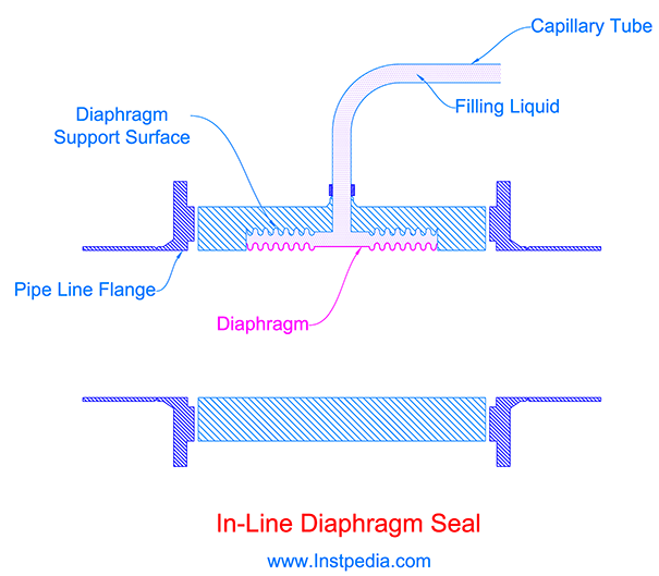
In-line diaphragm seal could be used for services that the medium is slurry, viscous, contains solid particles or has melting or freezing point at normal ambient temperature.
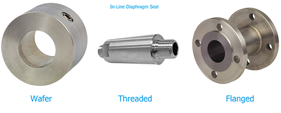
In-line diaphragm seal connections to the line pipe could be threaded, flanged, wafer or welded.
Diaphragm Seal Filling Liquid
Diaphragm seal filling liquid should have low viscosity, low thermal expansion coefficient, low vapour pressure and most importantly should be stable in the operating temperature range.
At high temperature, filling liquid might be vaporized and affect the true pressure measurement.
At very low and frigid temperature, filling liquid might become very viscous or even turn into solid.
Therefore the most important point in filling liquid selection is its stability operating temperature.
Filling liquids are available with temperature range from -90 ℃ up to 350℃.
Glycerin and Silicone Oil are the most common filling liquids.
In cryogenic ambient conditions Silicone Oil has better performance due to having low viscosity even in cold temperatures.
But Glycerin and Silicone Oil shall not be used for strong oxidizing agents such as Oxygen, Chlorine, Nitric Acid and Hydrogen Peroxide.
For these process fluids, Fluorinated or Chlorinated liquids such as Halocarbon or Fluorolube should be used.
For hygiene services especially in food industries for safety in case of leakage, Food grade Silicon Oil, Mineral Oil or Glycerin / Water should be used.
For vacuum services, filling liquid vapour pressure should be considered.
Over-Pressure Protection
Over pressure protection devices (Pressure Limiter Valves) are installed between the instrument and process connection and prevent the passage of excessive pressure beyond the maximum tolerable pressure limit of the instrument into the instrument element.
As mentioned formerly in pressure gauge range selection topic, if the process design pressure is more than the value of 1.3 x maximum scale, then over range protection device should be used to protect the pressure gauge from damage or burst.
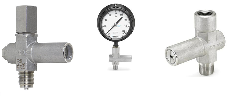
ASME B40.6 Standard has provided deferent types of over range protection devices, which are:
- Piston
- Diaphragm
- Relief Valve
- Bellows
Piston over pressure protection
This type of over pressure protection device consists of a piston and a set point adjusting spring.
In normal pressure condition the spring pushes the piston in a way that the inlet passage to the device outlet is open.
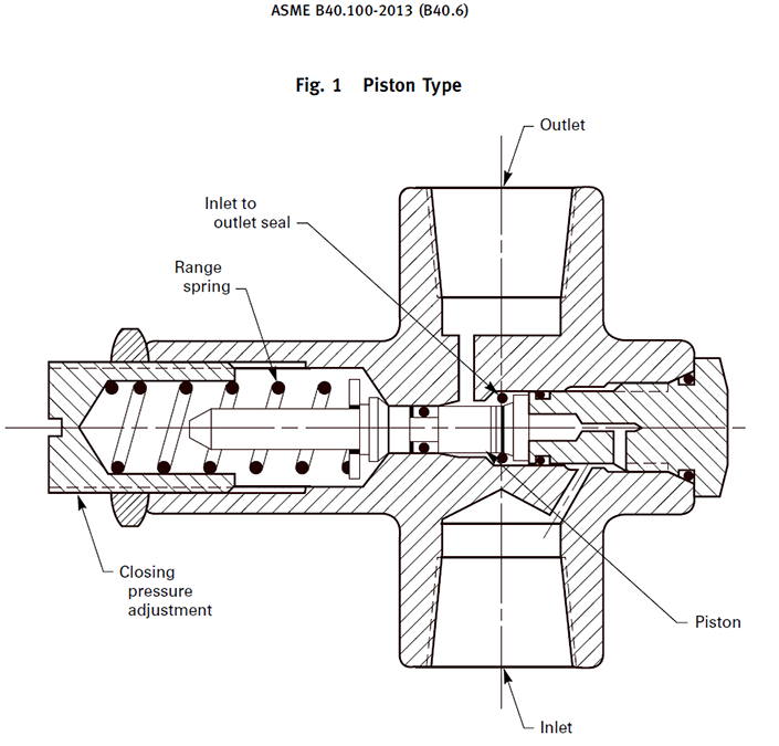
As the pressure reaches the excessive pressure that the spring is set for it, the process pressure force overcomes the spring force and pushes the piston against the spring which cause the device outlet blockage.
This action blocks the instrument connection to the process until the pressure is back to normal tolerable value.
Diaphragm over pressure protection
In this type of over pressure protection device the process pressure is sensed by a diaphragm.
Diaphragm over pressure protection has an adjusting spring that provides the force behind the diaphragm.
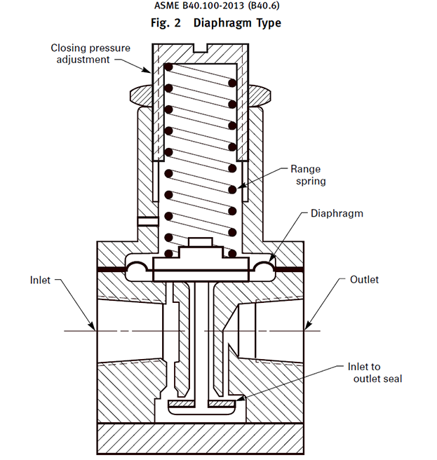
As the pressure reaches the excessive pressure, the process pressure force overcomes the spring force and pushes the diaphragm against the spring which cause the device outlet blockage.
Relief valve over pressure protection
Relief valve type consists of an adjustable range relief valve on instrument side and a check valve in its inlet.
As the pressure reaches the relief valve's set point pressure (excessive pressure), the relief valve opens and vents to the atmosphere and the check valve closes the inlet.
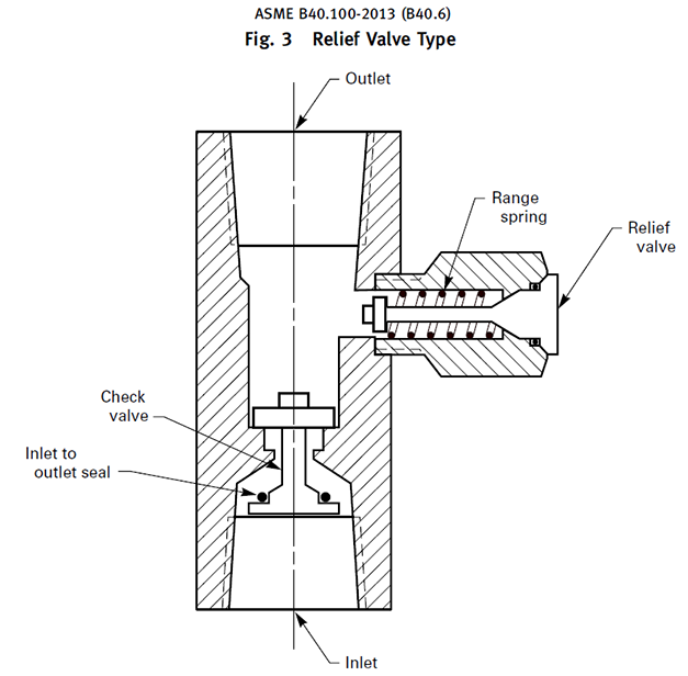
Relief valve over protection device is not applicable with diaphragm seal.
Bellows over pressure protection
In Bellow type consists of an adjustable range spring and a bellows.
If the system pressure force overcomes the spring force, the bellows blocks the inlet.
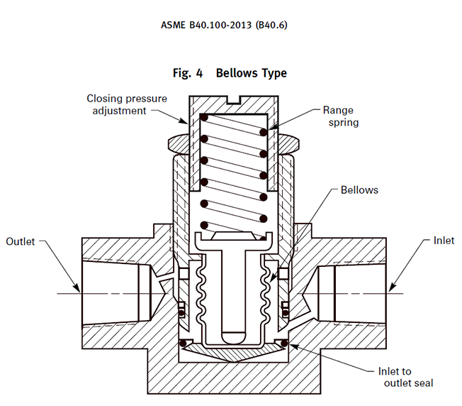
The advantage of this design is that the spring bonnet is completely isolated from the process medium, therefore it is suitable for fugitive or toxic services.
Snubber
Pressure surges in fluctuating services may damage the pressure measurement instruments.
Snubber is used to restrict or damp the pressure surges and spikes to protect the pressure instrument.
The basic operating principle of snubber is to provide a restriction orifice that restricts the surges passage to the instrument.
ASME B40.5 has specified different types of snubber as:
- Fixed Orifice
- Valve
- Porous Metal
- Felt plug – Fluid filled
- Piston (Pulsation Dampener)
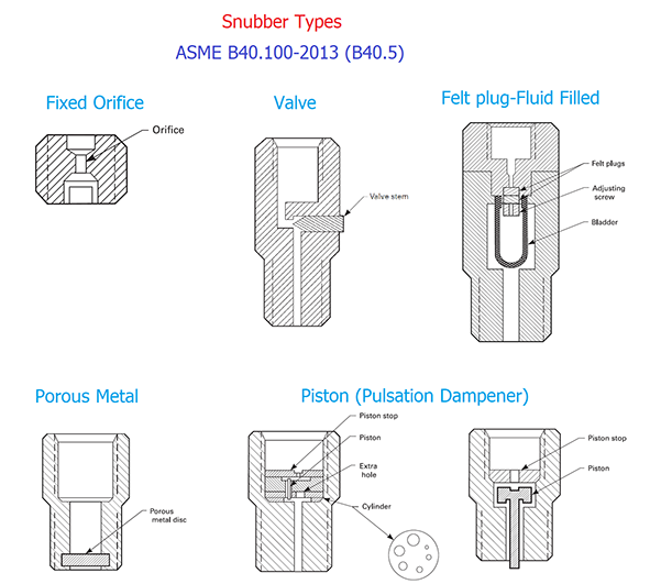
Fixed Orifice type is not adjustable but it could be used with different orifice sizes, proportional to the application fluctuating pressure.
Valve snubber could be adjustable by opening or closing the valve which in fact changes the orifice size of the snubber.
Porous snubber consists of a metal porous disk that damps the surges by slowing the flow while passing through its meshes and should not be used for services that containing solid particle.
Piston type consists of moving piston and an orifice.
The clearance or the capacity between the piston and the orifice has the main role in damping the pressure surges.
By changing the piston type and increasing this capacity, the amount of dampening increases.
The piping equipment, Pulsation Dampener, is a volume tank which is usually installed after pumps to damp the fluctuations and surges by expanding the medium in the tank.
Piston snubber operation is very similar to this piping equipment, hence it is called Pulsation Dampener.
Piston snubber is design in way that it is a self-cleaning device.
Felt plug – Fluid filled construction is similar to diaphragm seal.
It consists of a bladder or diaphragm and a felt plug.
The same as diaphragm seal assembly, the space between diaphragm and instrument element is filled with especial liquid.
Pressure surge pushes the diaphragm and makes the felt plug to be compressed which results in dampening the surge.

Snubber should be used for instruments at discharge line of reciprocating pumps and compressors.
Using snubber for instruments on the discharge line of centrifugal pumps is not necessary.
Differential Pressure Gauge
Differential Pressure Gauge indicates the difference between pressures of two points in the system.
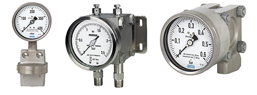
Mostly it is used to indicate the differential pressure between inlet an outlet of filters or strainers.
If the indicating differential pressure exceeds from a specific value, it means that the filter or strainer is blocked and needs to be cleaned or replaced.
There are some other applications for differential pressure gauges such as local level indication for tanks with blanketing gas or firefighting foam bladder tanks.
Differential Pressure Gauge Types
There are two common types of differential pressure gauges:
- Piston
- Diaphragm
Piston Differential Pressure Gauge
Piston Differential Pressure Gauge consists of a magnetic piston in a cylinder which separates medium of Low Pressure (LP) side from High Pressure (HP) side.
Beside the cylinder a magnetic ring which is connected to the pointer shaft, turns in relation with the piston position.
The piston moves in the cylinder by forces of the flow from LP side and HP side; and its stop position is proportional to the differential pressure between LP and HP sides.
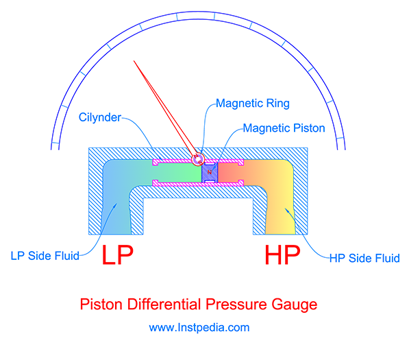
Differential Pressure unit is independent of the pressure measurement reference point.
It means that the terms; gauge and absolute are not applicable for differential pressure.
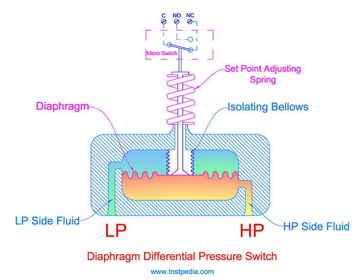
Diaphragm Differential Pressure Gauge
Diaphragm Differential Pressure Gauge operates by moving of a diaphragm that separates the Low Pressure (LP) side chamber from High Pressure (HP) side chamber.
Difference between pressure of LP and HP sides, changes the balance of the forces on the lower side and upper side of the diaphragm and cause the diaphragm to move.
Then the diaphragm displacement will be converted to rotary movement of the, using moving parts such as link, gear and pinion.
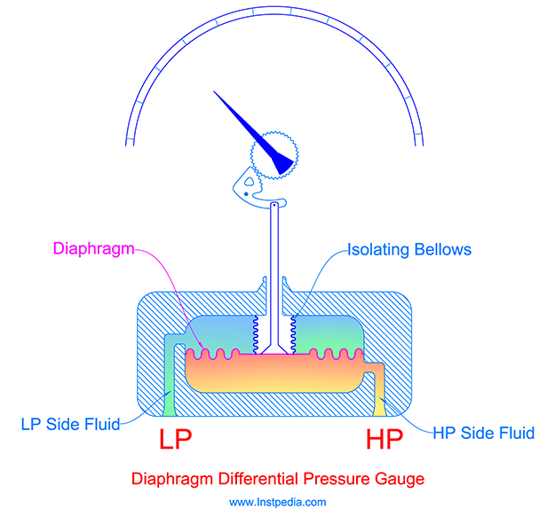
A metal flexible bellows isolates the moving parts from the process medium.
Differential Pressure Gauge Process Connections
Diaphragm Differential Pressure Gauge process connection is generally 1/2" or 1/4" NPT Male/Female that requires tubing and fitting for connection to the 5-valve manifold.
Differential Pressure Gauge Materials
Differential Pressure Gauge materials are similar to pressure gauges.
Case material
Plastic case is not suitable in industrial environments for differential pressure gauges.
AISI 316 / 316L and 304 / 304L Stainless Steels are the most proper and common materials for industrial differential pressure gauges case.
In areas with high density of oil & gas or petrochemical plants, the atmosphere might be polluted by corrosive gases which are not burned properly in flares and may change to a corrosive acid due to combination with ambient humidity.
In such environments AISI 316 is the best choice for case material.
Wetted parts material
AISI 316 / 316L / 316Ti Stainless Steels could be the best material for wetted parts due to proper resistance against corrosive services and acceptable mechanical properties with temperature range of -254 to 816°C.
For services that contain an aggressive species such as chloride (Cl-), like seawater, Austenitic Stainless Steels (316SS, 304SS …) are not applicable.
Alloys that have PREN (Pitting Resistance Equivalent Number) greater than 40 are recommended for such services.
Monel which is a Nickle- Copper alloy or Hastelloy C which is Nickle based alloy with molybdenum content are the suitable materials for wetted parts in seawater and chloride containing services.
Moving parts material
Moving parts are not in contact with the medium, but it is necessary to be stainless steel for long life expectancy of gauge.
Pointer material
Pointer material is usually from light Aluminum alloys.
Glass material
Differential pressure gauge glass for industrial applications should be shatterproof glass such as laminated safety glass or non-splintering plastic that will not shatter or splinter.
Caution for Acetylene
Acetylene forms explosive compounds with copper and copper alloys containing more than 70% copper.
Therefore special care should be taken for gauge material selection especially for wetted parts, moving parts or even fixators in the case to minimize the risk of explosion.
For example; Brass is a copper alloy which might be very common material for process connection and wetted parts in non-industrial water or air services, but using Brass in Acetylene service is forbidden.
It is recommended that the inscription ACETYLEN to be marked on the dial for differential pressure gauges in Acetylene service.
Differential Pressure Gauge Accuracy
Differential Pressure Gauge accuracy is 1.6% to 2% of full scale.
Differential Pressure Gauge Accessories
Differential Pressure Gauge accessories are 3-Valve manifold or 5-Valve manifold and mounting bracket.
Differential Pressure Gauge Range Selection
Process department provides the operating differential pressure of the two measuring points.
Differential pressure gauge range could be selected in a way that the given normal operating differential pressure to be at 40% to 60% of maximum scale value.
It is recommended to select a differential pressure range that maximum operating differential pressure does not exceed 75% of the maximum scale value.
Care should be taken that the differential pressure gauge could withstand the HP side pressure in case of LP side blockage.
This pressure is specified in gauge data sheets, as maximum operating static pressure or high overload safety pressure.
For example if the HP side pressure is 100barg and the LP is assumed to be 94 to 100barg, the differential pressure range could be selected from 0 to 10 bar but the gauge's maximum operating static pressure or high overload safety pressure should be more than 100bar.
Pressure Switch
Pressure Switches are pressure measurement instruments that sense the pressure mechanically and as the pressure reaches a predefined value, actuate a switch contact.
Closing or opening the switch contact in an electronic circuit provides a digital signal that could be used for an alarm or initiating of a process interlock.
Pressure switches do not have self-checking, therefore their reliability is not sufficient for critical control systems such as Emergency Shut Down system (ESD).
For this reason, they are rarely used in oil, gas and petrochemical industries.
Pressure element of pressure switches are very similar to pressure gauges' element.
Different types of pressure switches are:
- Bourdon
- Diaphragm
- Bellows
- Piston
Bourdon Pressure Switch
Bourdon Pressure Switch operation is the same as bourdon pressure gauge and the bourdon movement opens or closes a micro switch at a defined pressure set point.
Set point can be adjusted with an adjusting lever inside of the case.
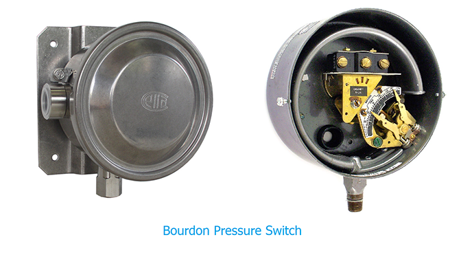
Pressure switch could have dial and pointer the same as pressure gauge for pressure indication, also could have another adjusting pointer for switch pressure set point adjustment.
This device is known as Pressure Indicating Switch.
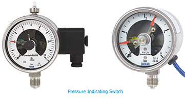
Pressure Indicating Switch is an economical device that provides pressure indication and pressure switch together in one device.
Bourdon pressure switch is not as accurate as diaphragm and bellows pressure switches and it is not recommended for critical control logics.
Diaphragm Pressure Switch
Diaphragm Pressure Switch construction is the same as diaphragm pressure gauge, but diaphragm movement instead of pointer rotation, actuates a micro switch.
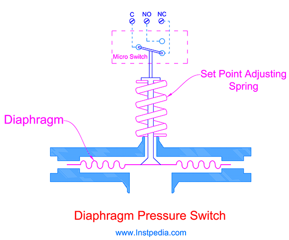
Diaphragm pressure switch accuracy is about 1% of full scale.
Diaphragm pressure switch itself, is not suitable for high pressure applications, but in contemporary designs with combination of diaphragm and piston, larger pressure range from vacuum up to 500bar are achieved.
Diaphragm Pressure Switch type could be the best selection in medium pressure range industrial applications.
Bellows Pressure Switch
Bellows Pressure Switch construction is the same as bellows pressure gauge and the bellows movement actuates a micro switch.
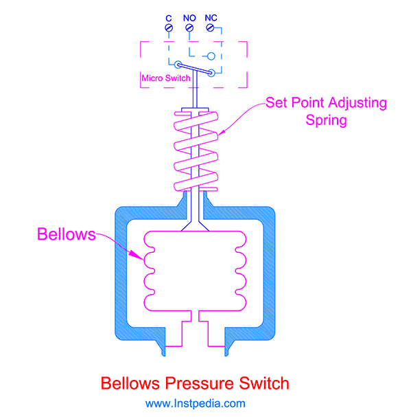
Bellows displacement is not linear, therefore it is not recommended for accurate process controls.
Piston Pressure Switch
Piston Pressure Switch consists of a piston which can move by process pressure force.
Piston displacement actuates a micro switch.
The piston shaft is sealed by O-ring seals that may wear and requires maintenance which decreases its reliability.
For this reason piston pressure switches are rarely used oil & gas industries.
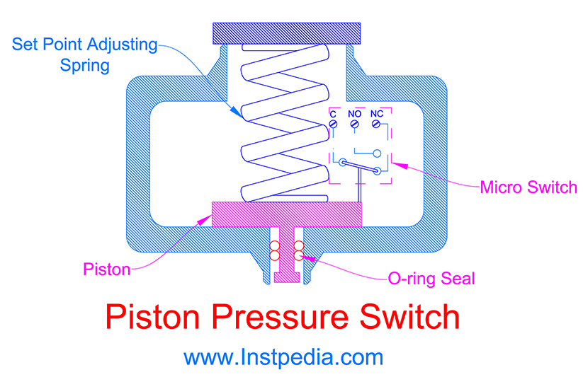
Piston pressure switches are used for high pressure applications especially hydraulic applications.
Switch Contact Types
There are four basic types of switch contacts:
- SPST (Single Pole Single Throw)
- SPDT (Single Pole Double Throw)
- DPST (Double Pole Single Throw)
- DPDT (Double Pole Single Throw)
SPDT and DPDT are the most frequently used switches for pressure switches.
This classification is based on the number of Poles and Throws that defines their connection type.
Before describing the switches contact types, we need to know the following definitions.
- Pole
- Indicates the switch contact sets.
- For example Double Pole means that the switch has two contact set that can be actuated at the same time.
- Throw
- Indicates the number of conducting positions.
- NO (Normally Open) contact
- NO contact is open in normal situation and do not pass throw the circuit current; and will be closed and allow the circuit current if it is energized or actuated.
- NC (Normally Close) contact
- NC contact is closed in normal situation and allow the circuit current normally; and if it is energized or actuated it will opens the circuit and interrupts the current.
SPST (Single Pole Single Throw)
SPST (Single Pole Single Throw) is the simplest switch contact type.
It has two terminals and break or connect between these two terminals.
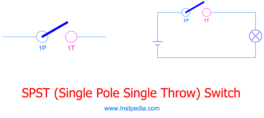
SPST switch is known as on/off switch.
SPDT (Single Pole Double Throw)
SPDT (Single Pole Double Throw) switch has three terminals.
One terminal is as the input and the other two terminals are the outputs.
It has one pole which when it is actuated, changes over between the two conducting position and can control two circuits with one common source.
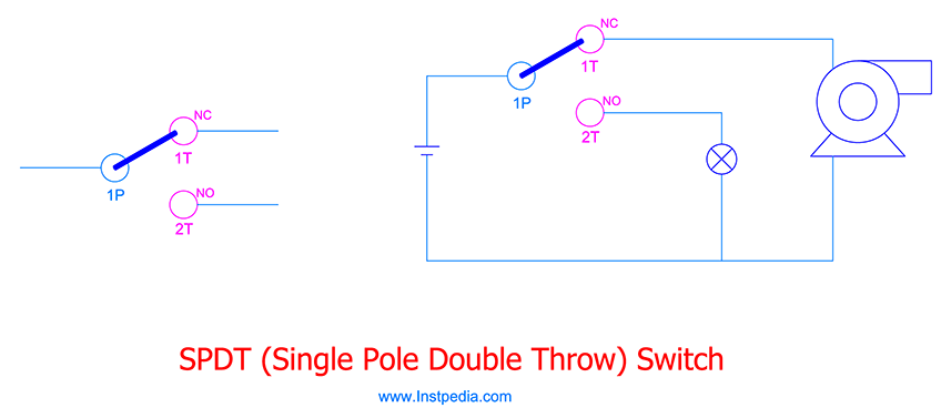
One of the conducting positions is NC (Normally Close) while the other one is NO (Normally Open).
DPST (Double Pole Single Throw)
DPST (Double Pole Single Throw) has two poles and for each pole it has one throw or conducting position.
The poles are actuated together at the same time.
It is similar to integration of two SPST switches that actuate at the same time with the same signal or mechanical action.
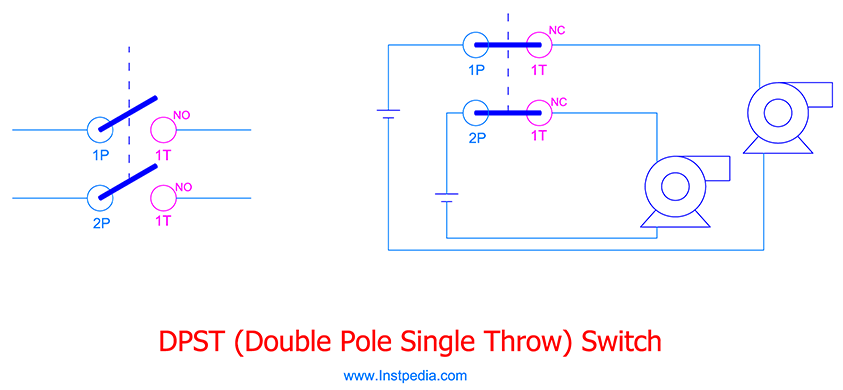
DPST switch can control two independent circuits with the same actuation source.
It has four terminals; two discrete inputs and two discrete outputs.
DPDT (Double Pole Double Throw)
DPDT (Double Pole Double Throw) has two poles and for each pole it has two throws or conducting positions.
DPDT is two synchronized SPDT switches that their poles are actuated together at the same time with the same action.
It has six terminals; two independent inputs and four independent outputs.
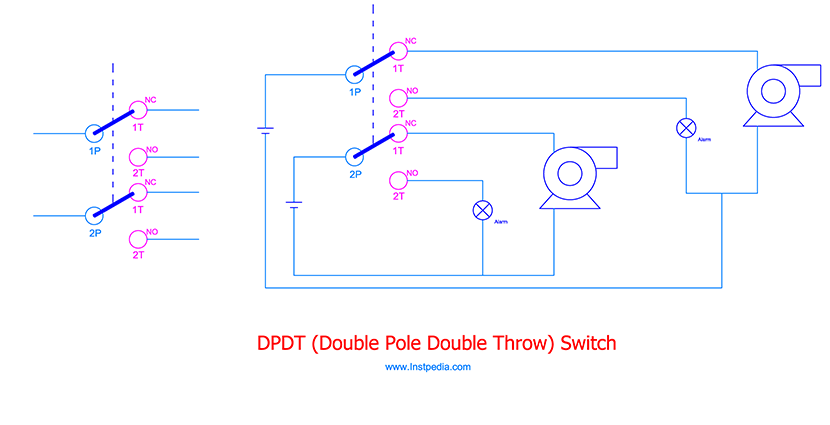
DPDT contact can control four independent circuits and changes over from two circuits to two other circuits.
Switch Contact Selection
In humid or corrosive environments, contacts are subject to oxidation or sulfidation.
Contact corrosion cause increase in contact electrical resistance which is not acceptable for most of control systems and low voltage circuits.
Solution is to use the following contacts:
- Hermetically sealed contact
- Gold contact
- Silver contact
- Self-cleaning contact
Hermetically sealed contacts are tightly sealed with inert gas and are immune from corrosion.
In Gold contacts a layer of gold covers the contacts as a passivation layer that protects the contact from corrosion.
Gold contact should be used for low current circuits which the electrical current will not exceed 0.4A, because in higher rating contacts the gold layer might melt.
Silver has low electrical resistance and it is cheaper than gold, therefore could be used as passivation layer for contacts.
Self-cleaning contact have a wiping action that removes the oxidation layers of the contact.
Pressure Switch Range Selection
Pressure switch range is the pressure range that its set point can be adjusted.
Set point is the predetermined pressure that actuates the switch contact to open or close positions.
Pressure switch could be adjusted to actuate the switch contact at the set point on rising or falling of the pressure.
Dead band is the difference between set point and reset point.
For example if a pressure switch set point is 10bar on rising pressure to turn off a pump, when the pump starts and pressure increases and reaches 10bar, the switch contact will be closed and pump trip signal will be sent to the control system.
Now if the pressure decreases from 10bar, when it reaches 9bar the switch contact will be opened and the pump trip signal will be removed.
In this system dead band is difference between set point pressure (10bar) and reset pressure (9bar) which is 1bar.
Dead band can be adjustable for most of pressure switches.
For selecting the pressure switch adjustable range, accuracy and service life should be considered.
But accuracy and service life are in contrast with each other.
In order to have the best accuracy, set point should be adjusted in upper half of the range.
For a long service life, set point should be adjusted in lower half of the range.
Solution to have optimum accuracy and long service life is to adjust the set point in middle 30% of the range.
In another word an adjustable range should be selected that the set point pressure is in its middle 30%.
Pressure Switch Materials
Plastic case is not suitable for industrial environments and AISI 316 / 316L and 304 / 304L Stainless Steels are the most proper and common materials for industrial pressure switches case.
AISI 316 / 316L / 316Ti Stainless Steels could be the best material for wetted parts due to proper resistance against corrosive services and acceptable mechanical properties with temperature range of -254 to 816°C.
For services that contain an aggressive species such as chloride (Cl-), like seawater, Austenitic Stainless Steels (316SS, 304SS …) are not applicable.
Alloys that have PREN (Pitting Resistance Equivalent Number) greater than 40 are recommended for such services.
Monel which is a Nickle- Copper alloy or Hastelloy C which is Nickle based alloy with molybdenum content are the suitable materials for wetted parts in seawater and chloride containing services.
Differential Pressure Switch
Differential Pressure Switch works the same as pressure switch, but it senses pressure of two points and the set point is a defined difference between pressures of the two points.
When the difference pressure reaches the set point pressure, the switch contact is actuated.
SPDT or DPDT are the most frequent used switches for differential switches, which are described formerly in Switch Contact Types topic.
Differential Pressure Switch types are:
- Diaphragm
- Bellows
- Piston
Diaphragm Differential Pressure Switch
Diaphragm Differential Pressure Switch consists of a diaphragm located between two sensing pressure points.
The diaphragm movement is due to difference between pressures of two sensing points.
As the difference pressure reaches the predefined pressure (set point) the switch contact is actuated.
Diaphragm Differential Pressure Switch could be the best selection in medium pressure range industrial applications.
Bellows Differential Pressure Switch
Bellows Differential Pressure Switch has two bellows; one for low pressure side and one for high pressure side.
There is a spindle connected to both of the bellows which moves due to difference between the pressures of the two bellows.
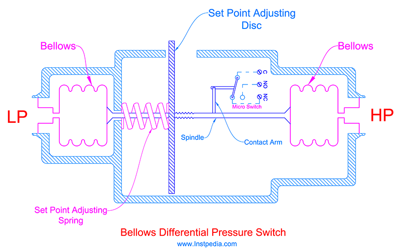
As the difference pressure reaches the predefined pressure (set point) the contact arm actuates the switch contact.
Piston Differential Pressure Switch
Piston Differential Pressure Switch consists of a piston which separates Low Pressure (LP) side medium from High Pressure (HP) in a cylinder.
The piston moves in the cylinder by forces of the flow from LP side and HP side; and its stop position is proportional to the differential pressure between LP and HP sides.
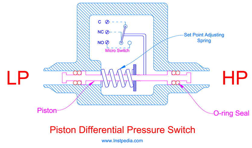
When the difference between LP and HP sides' pressures meets the set point, a micro switch will be actuated.
Sealing O-rings are the weakness of Piston differential pressure switch and are subject to leak or wear.
Piston differential pressure switches are used for high pressure applications especially hydraulic applications.
Differential Pressure Switch Range Selection
Differential pressure switch range should be selected in such a way that the adjusting set point to be in middle 30% of the range.
Set point is the predetermined differential pressure that actuates the switch contact to open or close positions.
Dead band is the difference between set point and reset point.
Dead band can be adjustable for some of differential pressure switches.
Care should be taken that the differential pressure switch could withstand the HP side pressure in case of LP side blockage.
Differential Pressure Switch Accuracy
Differential pressure switch accuracy is about 2% up to 3% of full scale.
Differential Pressure Switch Materials
Plastic case is not suitable for industrial environments and AISI 316 / 316L and 304 / 304L Stainless Steels are the most proper and common materials for industrial differential pressure switches case.
AISI 316 / 316L / 316Ti Stainless Steels could be the best material for wetted parts due to proper resistance against corrosive services and acceptable mechanical properties with temperature range of -254 to 816°C.
For services that contain an aggressive species such as chloride (Cl-), like seawater, Austenitic Stainless Steels (316SS, 304SS …) are not applicable.
Alloys that have PREN (Pitting Resistance Equivalent Number) greater than 40 are recommended for such services.
Monel which is a Nickle-Copper alloy or Hastelloy C which is Nickle based alloy with molybdenum content are suitable materials for wetted parts in seawater and chloride containing services.
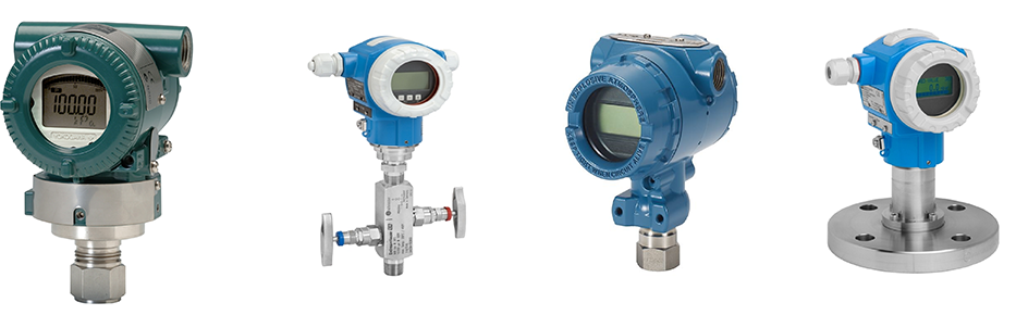
Pressure Transmitter
Pressure Transmitter has two main parts:
- Pressure sensing element
- Signal transmission part (Transducer)
Pressure sensing element converts the process pressure at the tapping point into a low level electronic signal.
The produced electronic signal needs to be amplified and translated to standard transmission signal as the transmitter output, which is usually 4 to 20mA signal.
Sensor is not in direct contact with the medium and the process pressure is transferred to the sensor through a diaphragm and filling liquid.
Pressure Sensing Element Types
The most common pressure sensing element types for pressure transmitters are:
- Electromechanical strain gauge
- Variable Capacitance
- Piezoresistive
- Piezoelectric
Electromechanical Strain Gauge Sensor
Strain gauges is a device that any deformation, bending or strain cause change in its electrical resistance.
If strain gauge is attached to an object, its electrical resistance change determines the strain on that object.
Strain gauge is used in a Wheatstone bridge for pressure measurement in pressure transmitters.
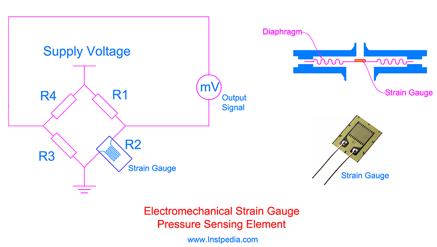
When the pressure is zero the resistive legs of the bride are balanced and there is no voltage differential across the bridge.
When a pressure is applied to the pressure transmitter, it strains the primary element with the attached strain gauge and causes its electrical resistance change.
Any change in strain gauge resistance, unbalance the Wheatstone bridge resistive legs and produces a voltage differential across the bridge which is proportional to the applied pressure.
Transmitter's signal transmission part (Transducer) converts this voltage to 4-20mA signal.
Temperature variation may affect the measurement due to diaphragm or primary element thermal expansion which will be considered as strain by strain gauge.
Therefore care should be taken for strain gauge material selection in order to compensate diaphragm thermal expansion.
Variable Capacitance Sensor
Variable Capacitance Sensor operation is based on change in capacitance of a capacitor caused by diaphragm movement.
Capacitor consists of two parallel metal plates that its capacitance changes with variation in distance of the plates or the material between them.
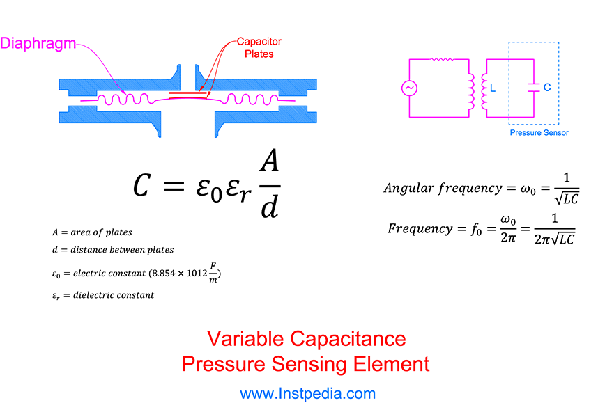
In variable capacitance sensor one of the plates is connected to the diaphragm and when the pressure is applied to the transmitter, it bugle the diaphragm which reduces the distance between the plates and changes the capacitance.
Pressure which is proportional to capacitance can be measured in an oscillator circuit (LC circuit) that frequency variation determines the capacitance change.
Piezoresistive Sensor
Piezoresistive Sensor is in fact the semiconductor technology of strain gauge.
Piezoresistive Sensor is a silicon base semiconductor that has been doped with other elements and its conductivity changes with extremely small stretch or deformation.
Piezoresistive Sensor is about 100 times more sensitive than metal electromechanical strain gauge sensor.
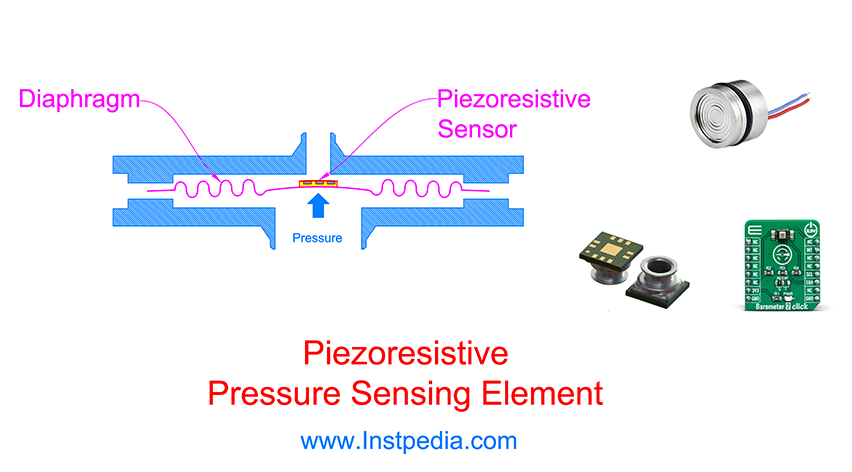
Piezoresistive Sensor is the most sensitive and accurate pressure sensor for pressure transmitters especially for very low pressure applications.
Piezoresistive Sensor is used in a Wheatstone bridge for pressure measurement in pressure transmitters.
Piezoelectric Sensor
Piezoelectric Sensor consists of a crystal that generates an electric charge when a force is applied across its faces.
When pressure is applied to a pressure transmitter with piezoelectric sensor, diaphragm compresses the crystal and a voltage proportional to the applied pressure will be generated.
The signal transmission part of the transmitter convert the generated voltage to a 4 - 20mA signal as the transmitter analogue output signal.
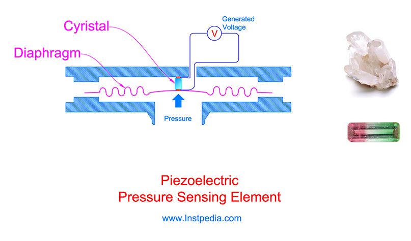
The piezoelectric sensor disadvantage is that it is not suitable for static pressure measurement because when the pressure is constant, the output signal gradually attenuates and falls to zero due to internal resistance or leakage.
But it is very sensitive to dynamic pressure.
The advantage of piezoelectric sensor is that it does not require any external power or current source.
The piezoelectric crystal could be natural crystals such as; Quartz, Rochelle salt and tourmaline or could be inorganic ceramics like; barium titanate or lead-zirconat.
Ceramic crystals have more sensitivity.
Absolute and Gauge Pressure Transmitters
As described in Pressure Types topic,the difference between absolute and gauge pressure measurement is the reference point which is considered as their zero point.
If the pressure of the opposite side of the diaphragm is absolute (perfect) vacuum and it is sealed, then the pressure transmitter measures the absolute pressure.
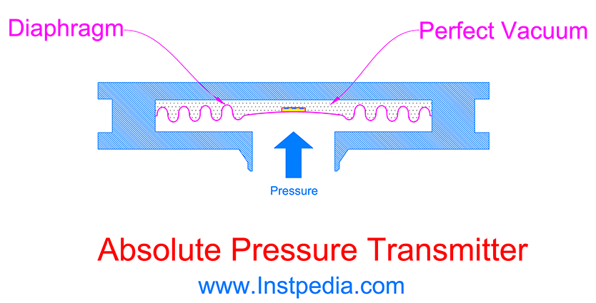
If the opposite side of the diaphragm is open to the ambient and has the atmospheric pressure, then the pressure transmitter measures the gauge pressure.
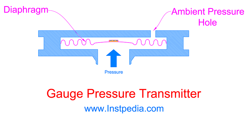
Pressure Transmitter Accuracy
Pressure transmitter accuracy is 0.015% to 0.155 of full scale.
Differential Pressure Transmitter
Differential Pressure Transmitter is used to measure the difference of pressure between two points.
Differential Pressure Transmitter operation is the same as pressure transmitter, but it has two pressure inlets (LP and HP) for connecting the two measuring point pressures.
LP and HP connections are located at opposite sides of the diaphragm.
The lower pressure point is connected to LP side and higher pressure point is connected to HP side.
The difference in pressures produces different forces on the sides of diaphragm and causes the diaphragm to fold to the LP side.
This movement of diaphragm is sensed by the sensor and converts to output signal as the differential pressure of the two measuring points.
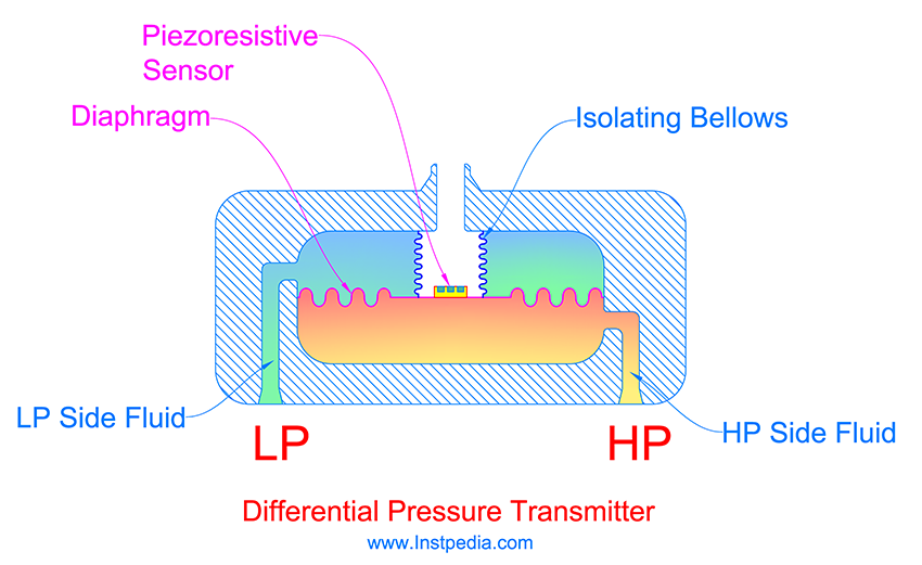
Sensor types for differential pressure transmitter are the same as sensors for pressure transmitters which have been described formerly.
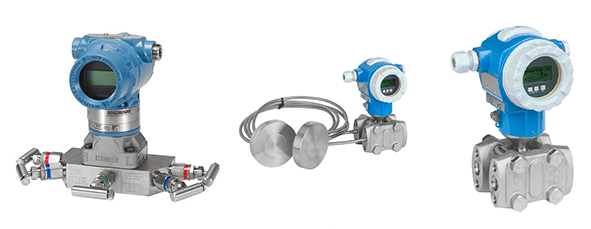
For this reason differential pressure transmitter accuracy is the same as pressure transmitter accuracy.
Pressure / Diff. Pressure Transmitter Materials
Plastic case is not suitable for industrial environments and AISI 316 / 316L and 304 / 304L Stainless Steels are the most proper and common materials for industrial pressure / diff. pressure transmitter case.
AISI 316 / 316L / 316Ti Stainless Steels could be the best material for wetted parts due to proper resistance against corrosive services and acceptable mechanical properties with temperature range of -254 to 816°C.
For services that contain an aggressive species such as chloride (Cl-), like seawater, Austenitic Stainless Steels (316SS, 304SS …) are not applicable.
Alloys that have PREN (Pitting Resistance Equivalent Number) greater than 40 are recommended for such services.
Monel which is a Nickle-Copper alloy or Hastelloy C which is Nickle based alloy with molybdenum content are suitable materials for wetted parts in seawater and chloride containing services.
Pressure / Diff. Pressure Transmitters Accessories
Required accessories for pressure or differential pressure transmitters, are manifold and diaphragm seal.
Manifold is an isolating device in addition to piping isolating valve on the process connection.
Number of isolating valves in manifold, is determined in relation to type of instrument.
Valve manifold and 2-valve manifold are used for pressure gauges and pressure transmitters, while 3-valve manifold and 5-valve manifold are used for differential pressure gauges and differential pressure transmitters.
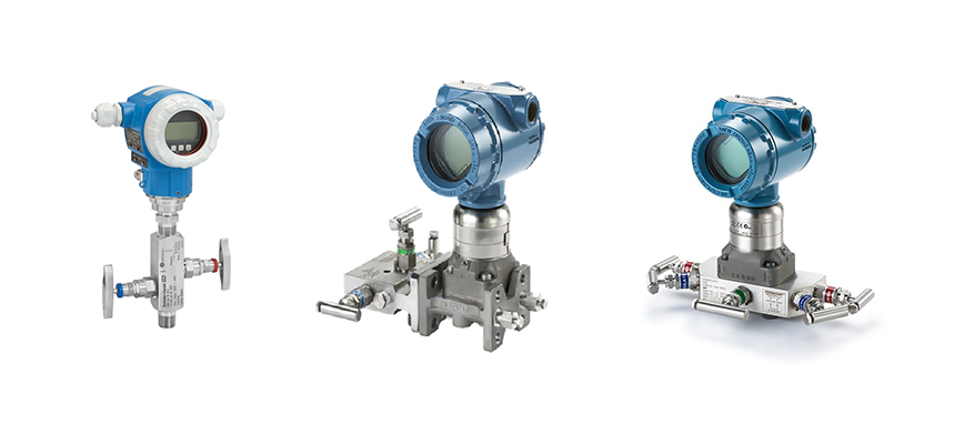
In some applications, in order to protect the pressure element, it should not be in direct contact with the medium.
As a solution, diaphragm seal which consists of a metal diaphragm will be installed on the process connection and the space between the diaphragm and pressure element will be filled with an especial liquid.
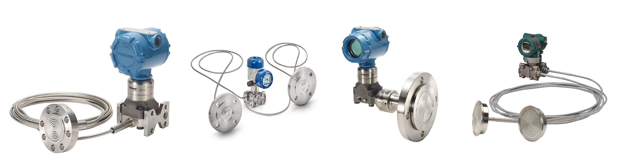
Therefore the pressure sensor is isolated from the medium and the line pressure is transferred by diaphragm to the filled liquid and finally to the sensor.
It is recommended to use diaphragm seal for the following services:
- Highly corrosive services
- Leakage is prohibited (toxic, explosive,… services)
- Very high temperature services
- Cryogenic services
- Hygiene services (food and drug industries)
- Dirty services
- Services containing solid particles
- Slurry services
- Very viscous services
- Services that fluid tends to be crystallized or polymerized
- Remote installation is required
There are two types of diaphragm seal; threaded and flanged.