Flow Measurement Instruments
Various Units of Flow Measurement
Flow is measured as a quantity (either volume or mass) per unit time.
- Liquid
- gpm, bbl/day, m3/hr, liters/min, etc.
- Gas or Vapor
- ft3/hr, m3/hr, etc.
- lb/hr, kg/hr, etc.
Volumetric units
Mass units (either liquid, gas or vapor)
Types of Flow Instruments
Flow meters are divided into three categories, based on measuring principle:
- Differential pressure (head)
- Mass flow
- Volumetric flow
Most common flow instruments of each category which will be described respectively are listed below:
Differential Pressure (Head) Type
Mass Type
Volumetric Type
As you see there are various types of flow measuring devices that may complicates the selection of appropriate device.
In the following you can find, summarized description of each flowmeter inclusive of measuring principle, accuracy, rangeability, advantages, disadvantages, installation requirements and best applications.
Differential Pressure (DP) Flowmeter
Differential pressure flowmeters, measure the flow rate based on Bernoulli's Law.
Daniel Bernoulli, a Swiss mathematician and physicist, published Bernoulli's principle in his book, Hydrodynamica, in 1738.
Bernoulli's principle states that, decrease of pressure or potential energy of a fluid in a closed system, causes an increase in fluid velocity.
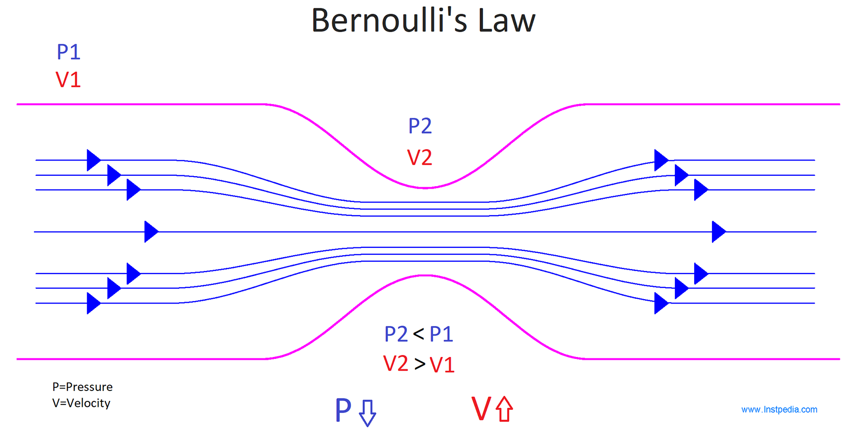
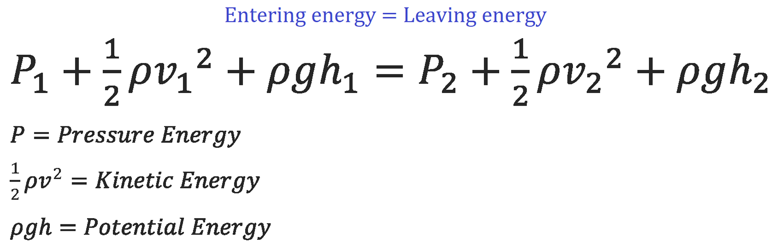
Bernoulli's principle can be derived from the principle of conservation of energy.
It states that the total energy of the fluid as it enters the system is equal to the total energy as it leaves.
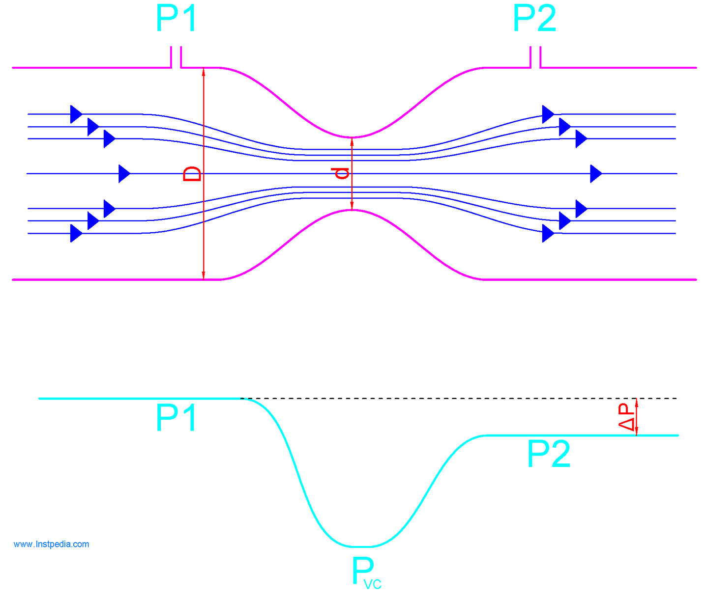
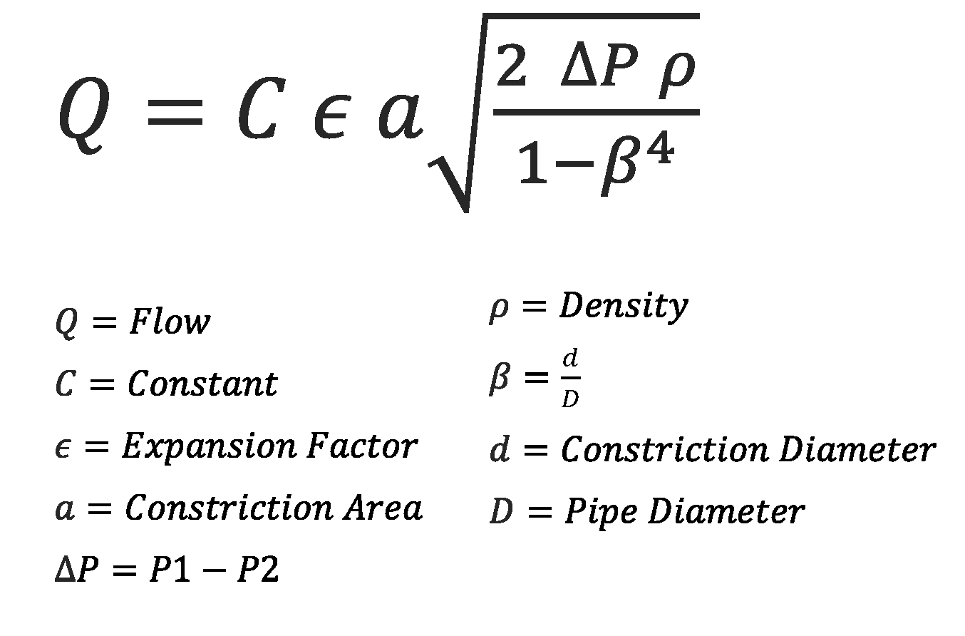
It can be derived from Bernoulli's Law, that pressure drop across the constriction is proportional to the square of the flow rate.
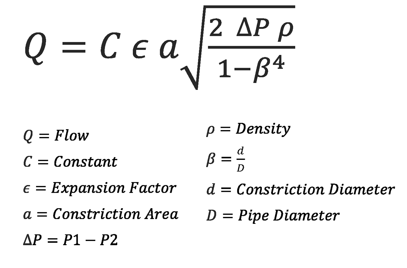
Based on this principal, Differential pressure flowmeters, prepare a specific constriction and measure the created pressure drop, then calculates the flow rate from the bellow equation:
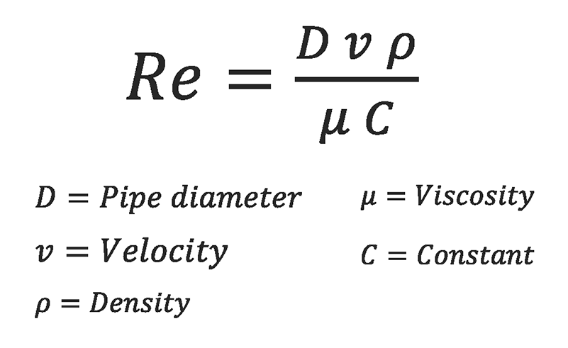
Reynolds Number
Osborne Reynolds, Irish-born British Physicist, demonstrated Reynolds Number, which is a dimensionless ratio to describe velocity and flow profile of the fluid.
It is a ratio of inertial forces to viscous forces of the liquid and it is defined as the following:
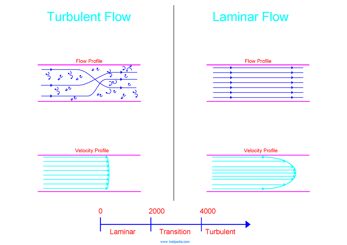
At very low velocities or high viscosities, Reynolds Number is low, and the liquid flows in smooth layers with the highest velocity at the center of the pipe and low velocities at the pipe wall where the viscous forces restrain it.
Flow profile with low Reynolds Number, is called Laminar Flow , and its velocity profile is parabolic.
At high velocities or low viscosities, Reynolds Number is high, and flow profile is chaotic with vortices and eddies.
This flow profile is called Turbulent Flow and velocity at center of the pipe is almost the same as the velocity near the pipe wall.
In addition to Reynolds Number, pipe wall friction has an important role to form the flow profile.
Most of flowmeters do not have their best accuracy in laminal flow condition, however they have an acceptable accuracy in turbulent flow condition.
Differential pressure flowmeters are one of those flowmeters.
In turbulent flow, pressure drop through a constriction is proportional to the square of the flowrate.
Therefore flow can be measured by using the above mentioned flow equation by differential pressure flowmeters.
In laminar flow, there is a linear relationship between flow and pressure drop.
Therefore the mentioned flow equation is not very accurate for flow measurement especially at low flow rates.
It means that Reynolds Number could be considered as an essential item for proper flowmeter selection.
Differential Pressure (Head) Type
Different types of DP flowmeters are defined based on their flow element, that how they prepare the constriction for pressure drop.
The following flow element types are the most common flow elements, used in a variety of industries:
- Orifice Plate
- Venturi Tube
- Flow Nozzle
- Wedge Meter
- V-Cone
- Pitot Tube
- Variable Area (Rotameter)
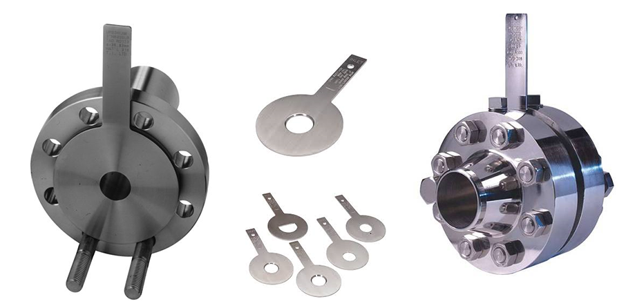
Orifice Plate
Orifice plate is a thin metal plate with a hole, which is installed in pipe line between flanges to provide a proper constriction and pressure drop for flow rate measurement.
The orifice bore size is calculated according to the required pressure drop and proportional to the measuring flow rate.
Different bore shapes are used in orifice plates considering media's characteristics and Reynolds Number.
ISO 5167 part 2 Standard, has specified orifice pates dimensional specification, which is the basis of orifice plates bore sizing and calculation.
Orifice Plate Bore Types
- Concentric
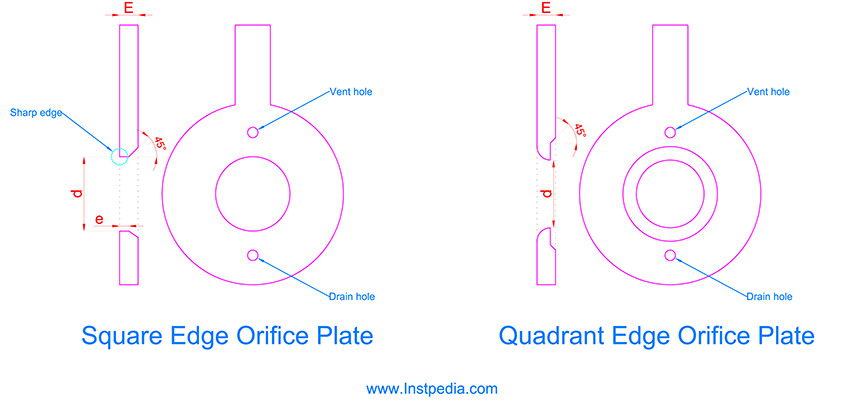
- Square Edge
- Quadrant Edge
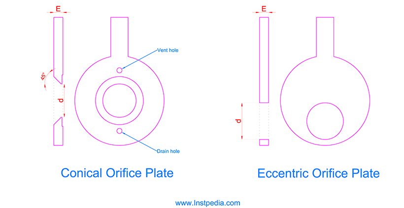
- Conical
- Eccentric
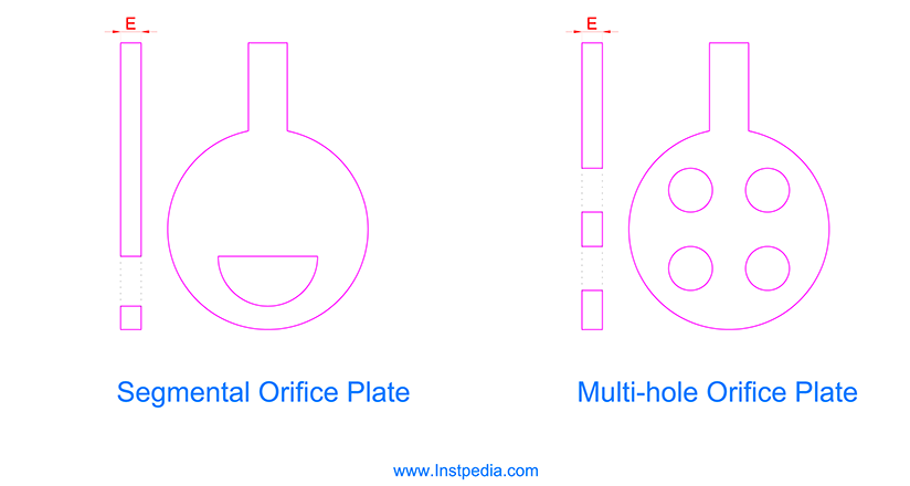
- Segmental
- Multi-hole (Conditioning)
Orifice Plate Selection
Concentric square edge orifice plate is the basic and standard orifice plate and it is most commonly used orifice plate.
In this orifice plate, the upstream face of the bore which the media enters the bore, has sharp edge. That’s why it is called Square Edge.
Square edge orifice plate can be used for non-viscous services with Reynolds Number greater than 2000.
Square edge orifice plate has not pipe size limitation and can be used for 1" up to 60" pipes.
Square edge orifice plate is not appropriate for erosive services.
For viscous services with low Reynolds Number, where square edge orifice plate don't give a good result in calculation, quadrant edge and conical orifice plates can be helpful.
Quadrant edge and conical orifice plates can be used for pipe sizes less than 6".
Concentric orifice plates (Square edge, Quadrant edge and Conical) shall be used for flow measurement of clean liquids and gases.
For dirty, multi-phase and slurry services, Eccentric and Segmental orifice plates are used.
Eccentric orifice plate is the same as centric one, but the hole has an off-set to the plate center.
Segmental orifice plate hole is a segment of a circle and cannot be used for vertical pipe lines.
Conditioning or multi-hole orifice plate is similar to concentric orifice plate however, it has more advantages such as:
- can be used without or with less upstream and downstream straight pipe length
- has less noise level
- reduces the pressure loss
- reduces eddies at downstream
- has better accuracy
- can be provided with compact tubing and transmitter assembly
- does not required vent and drain hole (Self-venting and draining)
The following table could be useful for orifice plate selection:
| Orifice Type | Reynold Number Range | Pipe size | Fluid Characteristics |
|---|---|---|---|
| Concentric Square Edge | Over 2000 | 1" to 60" | Clean, Turbulent |
| Concentric Quadrant Edge | 100 to 2000 | 1" to 6" | Clean, Viscous, Laminar |
| Concentric Conical | 50 to 100 | 1" to 6" | Clean, Viscous, Laminar |
| Eccentric | Over 10000 | 4" to 14" | Dirty, Slurry, Multi-Phase |
| Segmental | Over 10000 | 4" to 14" | Dirty, Slurry, Multi-Phase |
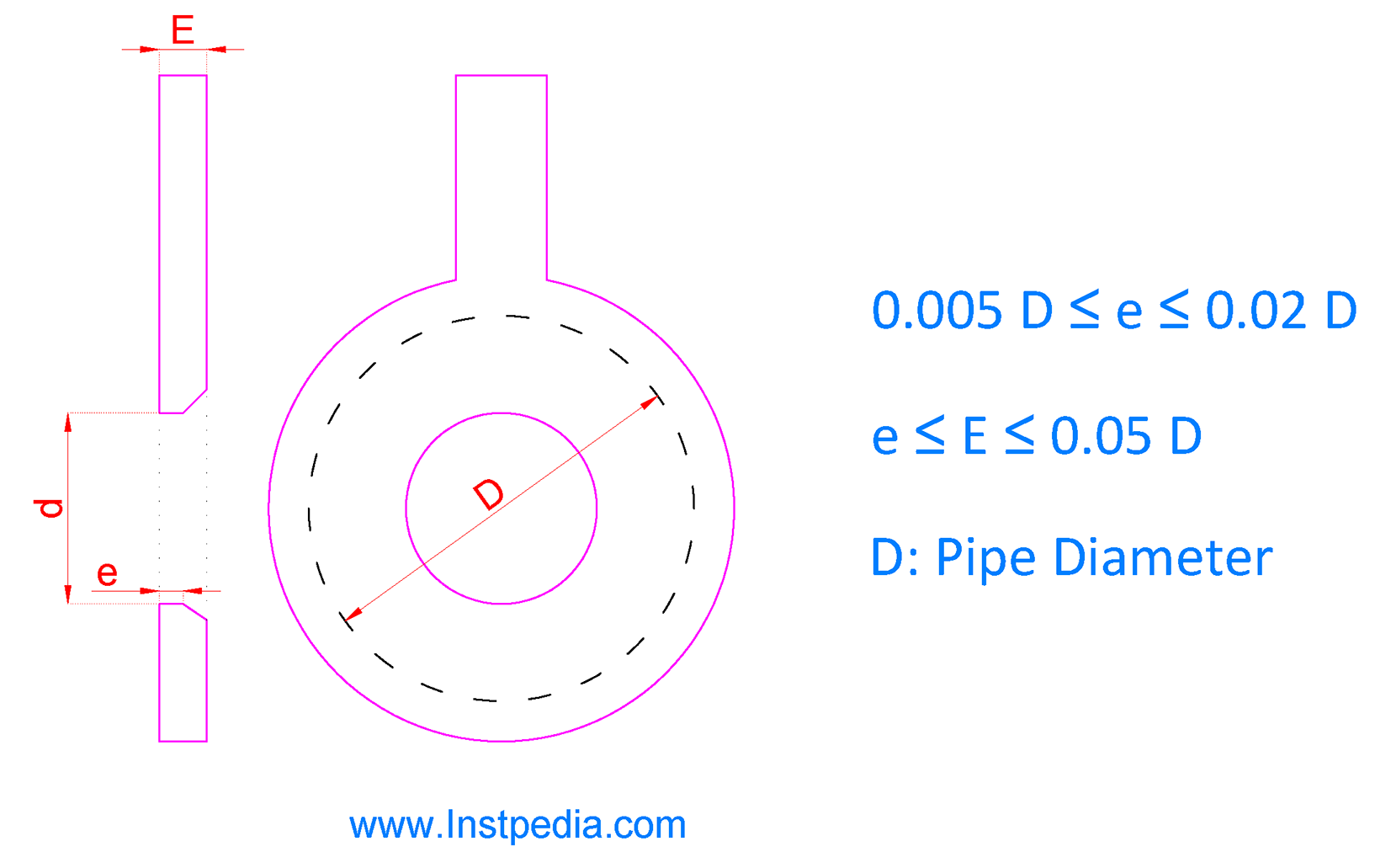
Vent hole for liquid services or drain hole for gas services should be considered for concentric orifice plates, if the bore diameter is more than 1", in order to avoid vapour or condense trapping behind the orifice plate.
Vent and drain hole diameter should not be more than 2mm.
Taps Location
In order to measure the differential pressure, two pressure taps (one on upstream and one on downstream of orifice plate) are required.
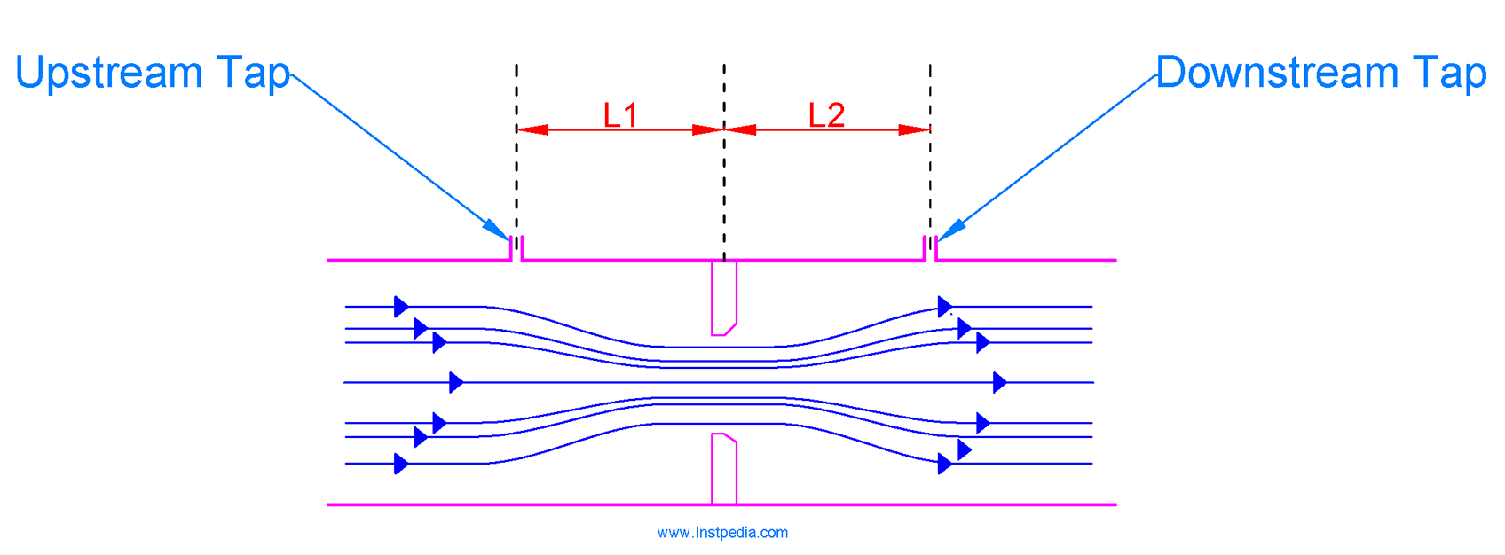
The common locations for pressure taps are:
- Flange
- Corner
- Radius
- Vena-Contracta
- Pipe (Full Flow) tap
Flange Tapping
Flange tapping is the most common pressure tapping for orifice plates larger than 2".
Taps are drilled by flange manufacturer in accordance with ASME B16.36, and the taps distance to orifice plate is 1" (25.4mm).
Minimum rating for orifice flanges is 300#.
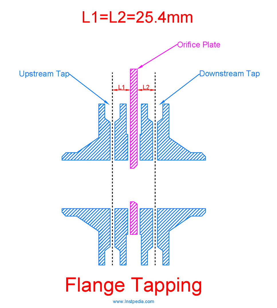
It is possible to have two tapping sets in order to use one orifice plate for two flow measuring systems, but to avoid mutual interference, tapping sets shall be offset by at least 30°.
The above figure shows a Double Tap Orifice Flange with two tapping sets.
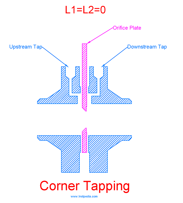
Corner Tapping
In corner tapping, taps are drilled on flanges similar to flange tapping, but the pressure is measured at the corner between pipe wall and the orifice plate.
Corner tapping is usually used for less than 2" pipe lines for conical or quadrant edge orifice plates in low flow or viscous services.
Radius Tapping
In radius tapping, taps are located on pipe line.
Upstream tap is located at one pipe diameter (1D) and downstream tap is located at one half pipe diameter (1/2D) from orifice plate.
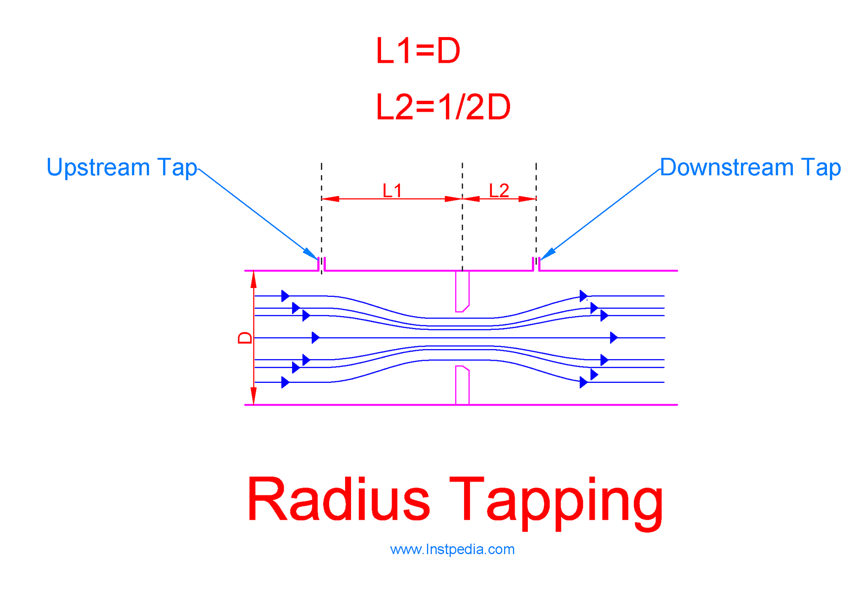
On services that diaphragm seal (chemical seal) shall be used for process connection, radius tapping can be used because of providing the sufficient space for diaphragm seals and its flanges in upstream and downstream of the orifice plate.
For example in some very toxic services, thread connection is prohibited, therefore radius tapping with diaphragm seal connection can be the solution for orifice plates instead of threaded flange tapping.
Vena-Contracta Tapping
Vena-contracta tapping and Radius tapping are very similar, but in vena-contracta the downstream tap is located at the point of minimum pressure which is called vena-contracta point.
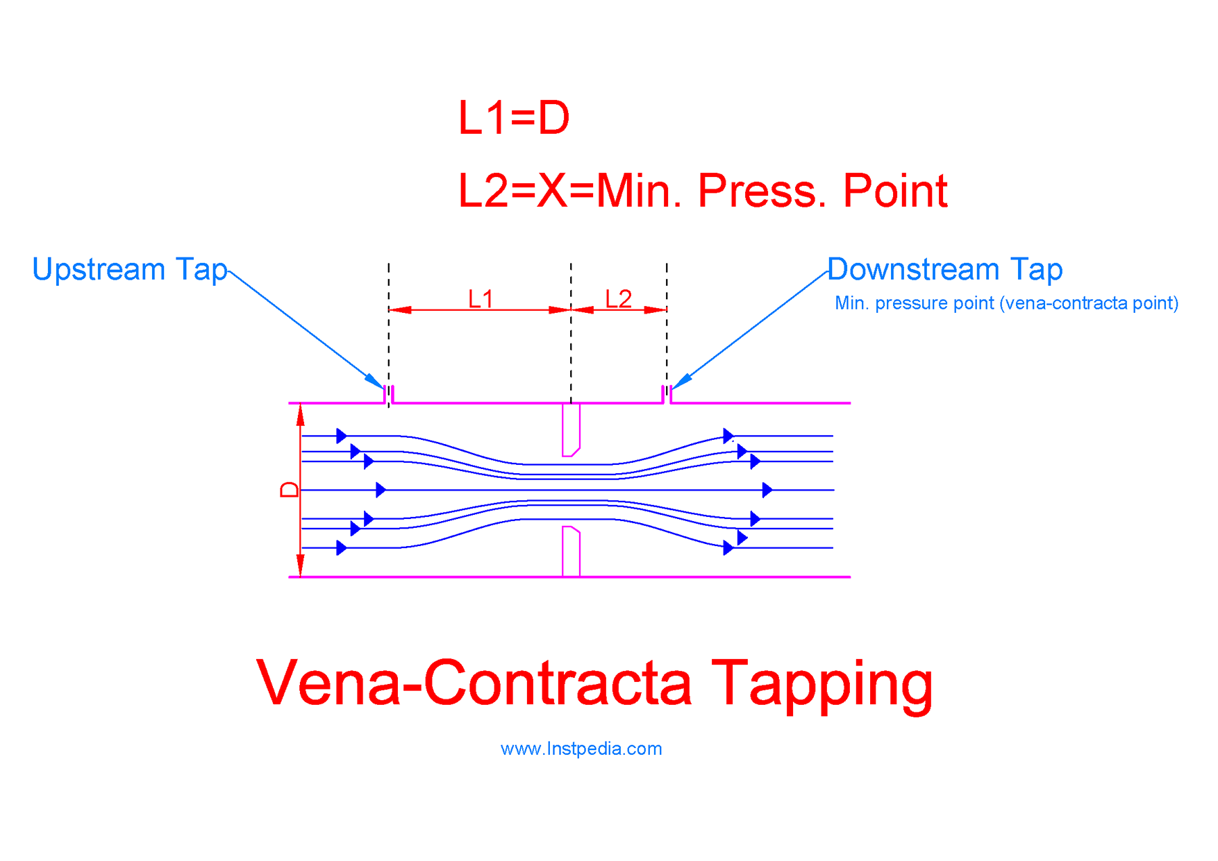
Vena-contracta location depends on β ratio.
β is the ratio or orifice plate bore diameter to pipe inside diameter.
In pipe lines smaller than 6", vena- contracta point is very close to the orifice flange that tapping is difficult, therefore vena-contracta tapping is used for pipe lines larger than 6".
Vena-contracta tapping provides the maximum pressure drop for flow measurement, if the downstream tap location is calculated precisely.
Pipe (Full Flow) Tapping
In pipe tapping, upstream tap is located at two and a half pipe diameter (2.5D) and downstream tap is at eight pipe diameter (8D) from orifice plate.
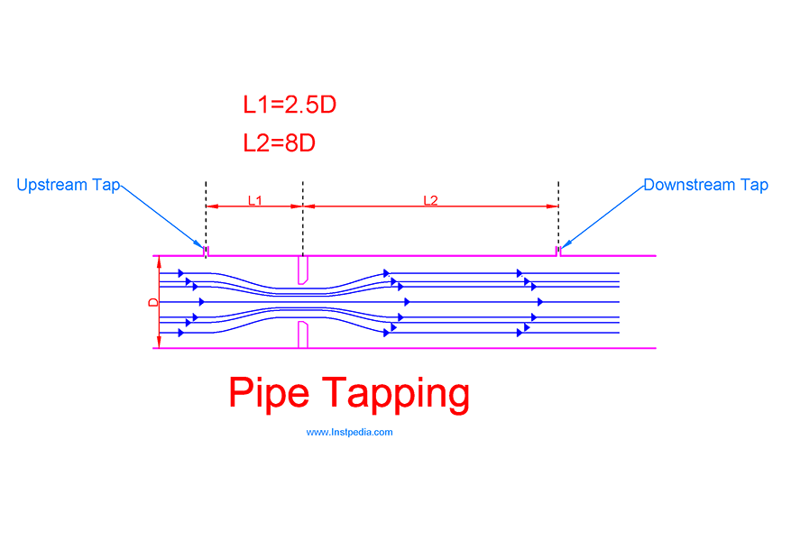
Because of the distance from orifice plate, taps location do not require precise calculation.
Pipe tapping detects minimum pressure drop, hence more error and inaccuracy is expected in flow measurement with this tapping design.
Tap Orientation
For liquid services, taps orientation shall be horizontal or up to 45° below the horizontal, in order to allow the trapped vapour to exit the impulse lines.
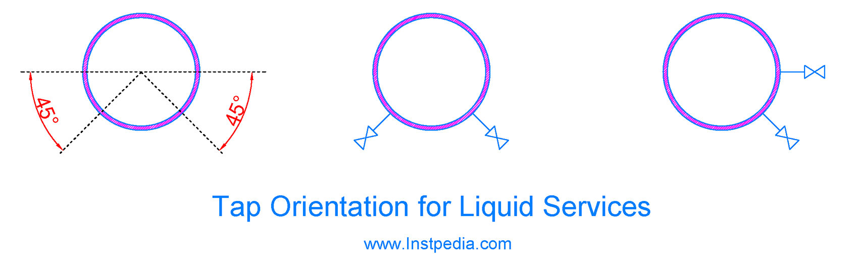
The taps orientation shall not be more than 45° below the horizontal, to avoid entering of sediment into impulse line.
DP transmitter should be located at a lower position than the taps for liquid services.
For gas services, taps orientation shall be vertical or within 45° of the vertical, in order to allow the moisture to drain out from the impulse lines.
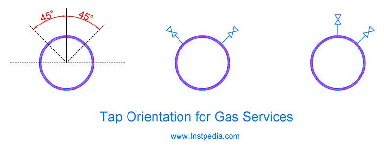
DP transmitter should be located at a higher position than the taps for gas services.
For steam services, taps orientation shall be horizontal or up to 45° above the horizontal, in order to allow the trapped vapour to exit the impulse lines which are filled with condensation.
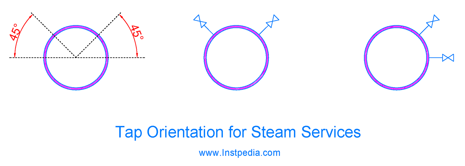
Orientation, the same as liquid services could be used for steam services, but in high velocity steam services, inaccuracy increases in tap orientation below the horizontal.
DP transmitter should be located at a lower position than the taps for steam services.
Condense pot could be provided at a close distance to the tap isolating valve which is filled with condensation or water to protect DP transmitter from high temperature steam.
Orifice Plate Thickness
Orifice plate shall have appropriate thickness and mechanical strength in order to withstand the flow impacts and forces without being crushed or deformed.
ISO 5167-2, determines standard orifice plate thickness as the following:
This table provides the typical orifice plate thicknesses for different pipe sizes:
| Pipe size | Plate Thickness mm(inch) |
|---|---|
| 2" to 6" | 3 mm (1/8") |
| 8" to 14" | 6 mm (1/4") |
| 16" to 24" | 9 mm (3/8") |
| over 26" | 12 mm (1/2") |
Orifice Plate Calculation
The purpose of orifice plate calculation is to calculate orifice bore size.
Orifice bore diameter (constriction diameter) should be sized to ensure that it can pass maximum considered flow rate and provides a proper pressure drop for measuring the flow rate with an acceptable accuracy.
If we take a look at the flow equation again, we can determine the inputs and outputs of the calculation.
We need to solve this equation for β which is ratio of bore diameter to pipe diameter.
Orifice plate calculation shall be in accordance with EN ISO 5167-2.
According to EN ISO 5167-2, bore diameter in all cases, shall be greater than or equal to 12.5mm and β ratio shall be always greater than or equal to 0.1 and less than or equal to 0.75.
Usually in projects technical specification in most of industries, allowable range of β ratio is 0.2 to 0.75 that fulfills the mentioned range in EN ISO 5167-2 standard.
Q is the maximum flow rate that could be passed through orifice bore. It is the upper limit of flow measuring scale.
It means that the DP flow transmitter cannot measure a flow rate higher than this flow rate with this orifice plate.
The required minimum, normal and maximum flowrates for calculation, will be specified by process department in orifice plate datasheet.
Q, the upper limit of flow scale of measuring device, shall cover this flow range that in case of changes in process condition and a minor increase in maximum flow, orifice plate and DP transmitter still could be able to measure the flow rate.
It is recommended to consider 10% over the maximum process flowrate for Q in orifice bore calculation.
Differential pressure value, ΔP, depends on DP transmitter sensor range.
Of course DP transmitters can be calibrated for any scale in their sensor range, but it is preferred to select manufacturers' standard ranges which are as the following:
50mbar, 100mbar, 125mbar, 250mbar and 500mbar.
Now, if the service process data and pipe line material are available, then the only unknown parameter in the equation is β ratio, which is calculation target.
Orifice Plate Calculation Summarized Tips
Orifice plate should be calculated using a primary flow element calculation software.
Flowel 4 software is recommended as a reliable and accurate software for orifice plate calculation.
As mentioned before are target is to solve flow equation for β ratio.
Preliminary Calculation inputs are:
- Pipe size, schedule and material
- Tapping type: Flange Tap
- Orifice plate: Square Edge
- Q = 110% of maximum process flowrate
- Δ P = 250mbar
- Operating temperature
- Density
- Viscosity
- Molecular weight (for gases)
- Vapour pressure (for cavitation calculation for liquids)
Calculation output is β ratio, which should be between 0.2 and 0.75.
β < 0.2
If β < 0.2 then the ΔP could be changed to 125mbar.
If β ratio is still below 0.2, then lower ΔP values down to 50mbar could be checked to have an in range β ratio, otherwise Reynold Number should be considered in order to change the orifice plate type to Quadrant Edge or Conical orifice plates.
Note that if orifice type is changed to Conical, then corner tapping should be selected.
β > 0.75
If β > 0.75 then change the ΔP to 500mbar.
Higher ΔP values are not recommended, because of the effect on accuracy for low flowrates.
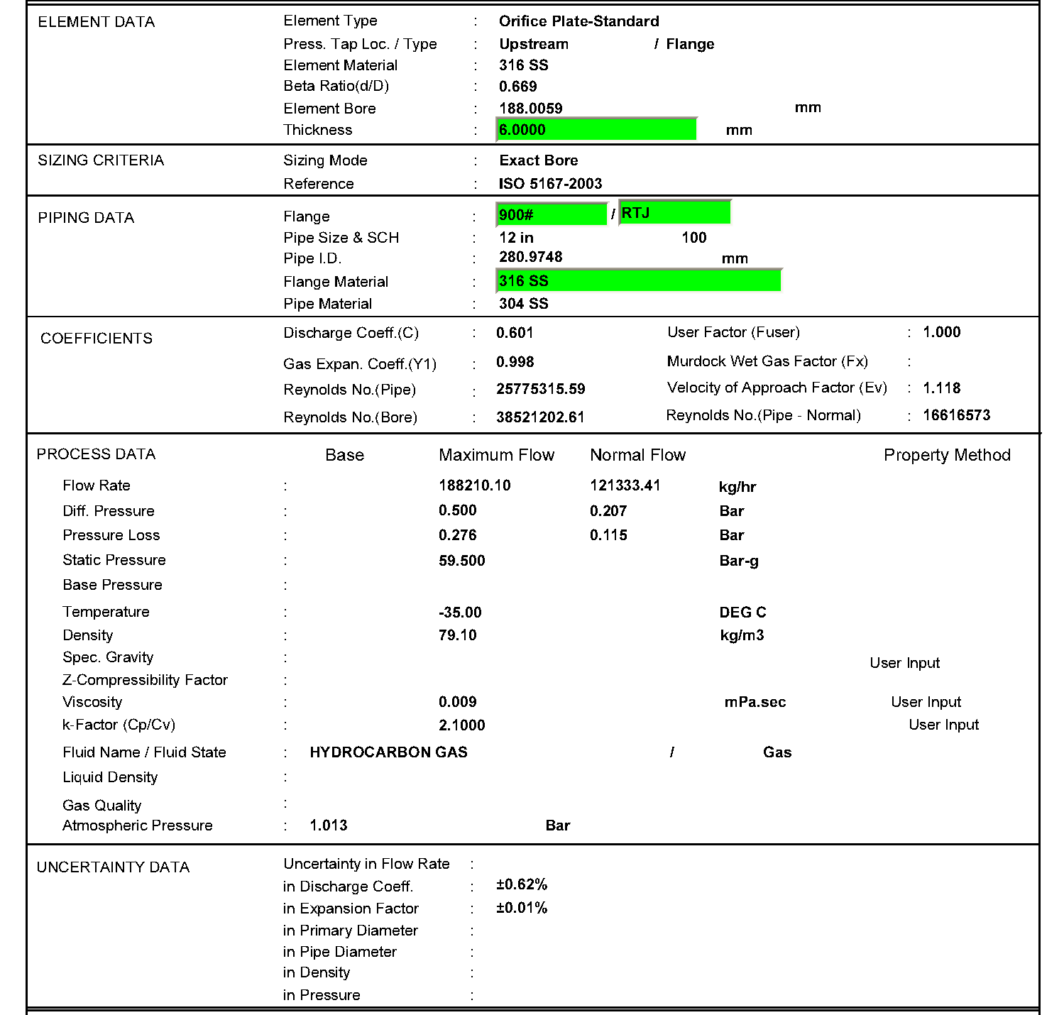
The following figure shows a sample orifice plate calculation sheet:
Orifice Plate Material
Corrosion resistance, mechanical strength and cost should be considered for orifice plate material selection.
AISI 316 Stainless Steel is the best material for orifice plate due to proper resistance against corrosive services and acceptable mechanical properties with temperature range of -254 to 816°C.
For services that contain an aggressive species such as chlorides (Cl-), like seawater, Duplex & Superduplex alloys that have PREN (Pitting Resistance Equivalent Number) greater than 40 are recommended.
For orifice flanges material, the document Piping Material Specification (PMS) of the project should be followed and usually it is the same as pipe material.
For carbon steel pipes, the most common orifice flange material could be as the following:
- ASTM A 105 (forged carbon steel): for pipe < 2", for Ambient / High Temperature (-29 to +476°C)
- ASTM A 216WCB (cast carbon steel): for pipe > 2" , for Ambient / High Temperature (-29 to +476°C)
- ASTM A352 LCB (forged carbon steel): for pipe < 2", for Low Temperature (-46°C)
- ASTM A 350 LF2 (cast carbon steel): for pipe > 2", for Low Temperature (-46°C)
Orifice Plate Required Straight Pipe Run
Orifice plate requires a stabilized and swirl free flow profile to provide the maximum accuracy.
Piping equipment and fittings may cause swirl, surge or eddies in the flow profile.
Therefore special care should be taken for orifice plate installation to have sufficient straight pipe line upstream of the orifice plate to let swirls or surges be damped and ensures having a natural and stable flow profile after that.
EN ISO 5167 has provided minimum upstream and downstream straight length for orifice plate installation as the following table:
| β | Upstream side of orifice plate | Downstream of orifice plate | ||||||||||||||||||||||||
|---|---|---|---|---|---|---|---|---|---|---|---|---|---|---|---|---|---|---|---|---|---|---|---|---|---|---|
| 1 Bend 90° / 2 Bends 90° any plane S>30D | 2 Bends 90° same plane S-config. 30D≥S>10D | 2 Bends 90° same plane S-config. 10D≥S | 2 Bends 90° perpendicular planes 30D≥S≥5D | 2 Bends 90° perpendicular planes 5D>S (note 5) | 1 Tee 90°- Mitre 90° bend | 1 Bend 45° / 2 Bends 45° same plane S-config. S≥2D | Concentric reducer 2D to D over a length of 1.5D to 3D | Concentric expander 0.5D to D over a length of D to 2D | Full bore ball valve or gate valve fully open | Abrupt symmetrical reduction | Thermowell diameter ≤0.03D (note 6,7) | Fittings and densitometer pocket | ||||||||||||||
| - | A | B | A | B | A | B | A | B | A | B | A | B | A | B | A | B | A | B | A | B | A | B | A | B | A | B |
| ≤0.20 | 6 | 3 | 10 | - | 10 | - | 19 | 18 | 34 | 17 | 3 | - | 7 | - | 5 | - | 6 | - | 12 | 6 | 30 | 15 | 5 | 3 | 4 | 2 |
| 0.40 | 16 | 3 | 10 | - | 10 | - | 44 | 18 | 50 | 25 | 9 | 3 | 30 | 9 | 5 | - | 12 | 8 | 12 | 6 | 30 | 15 | 5 | 3 | 6 | 3 |
| 0.50 | 22 | 9 | 18 | 10 | 22 | 10 | 44 | 18 | 75 | 34 | 19 | 9 | 30 | 18 | 8 | 5 | 20 | 9 | 12 | 6 | 30 | 15 | 5 | 3 | 6 | 3 |
| 0.60 | 42 | 13 | 30 | 18 | 42 | 18 | 44 | 18 | 65 (Note8) | 25 | 29 | 9 | 30 | 18 | 8 | 5 | 20 | 9 | 12 | 6 | 30 | 15 | 5 | 3 | 6 | 3 |
| 0.67 | 44 | 20 | 44 | 18 | 44 | 20 | 44 | 20 | 60 | 18 | 36 | 18 | 44 | 18 | 12 | 6 | 28 | 14 | 18 | 9 | 30 | 15 | 5 | 3 | 7 | 3.5 |
| 0.75 | 44 | 20 | 44 | 18 | 44 | 22 | 44 | 20 | 75 | 18 | 44 | 18 | 44 | 18 | 13 | 8 | 36 | 18 | 24 | 12 | 30 | 15 | 5 | 3 | 8 | 4 |
If there is not sufficient space available for the recommended straight pipe length upstream of the flow element, then flow conditioner could be used to damp the swirls or eddies in a very short pipe run.
Orifice Plate Accuracy
Parameters that affect flow measurement accuracy using Orifice plate are: discharge coefficient, fluid properties, flow condition and DP transmitter accuracy.
Discharge coefficient is the ratio of actual flow to theoretical flow which is considered in flow equation to gain the actual flow from the equation.
Reynolds Number has a major role in discharge coefficient.
For high Reynolds Number, effect of viscosity is negligible and can be ignored, but for low Reynolds Numbers, it affects discharge coefficient and flow computation.
Fluid properties affect the accuracy in conversion of volumetric flow to mass flow calculation.
Physical fluid properties like isentropic exponent, k, in compressible fluids which is function of temperature and in some cases operating pressure affect the density, which is important for mass flow calculation.
As mentioned before, piping equipment at upstream of flow element can cause distortion and swirls in flow profile, which affects the flow measurement accuracy.
By using proper straight pipe run length at upstream of the flow element or flow conditioner, effects of flow condition on accuracy could be minimized.
Today's DP transmitters have been developed a lot to minimize the errors and inaccuracy of measuring and processing, therefore their total inaccuracy could be 0.1% of span.
As a conclusion, considering all the mentioned parameters and solutions for minimizing the inaccuracies, the best obtained flow measurement accuracy for the whole set of orifice plate and DP transmitter could be 1% of span.
Orifice Plate Rangeability
Rangeability or turndown ratio is the ratio of maximum to minimum measurable flow rate with the defined accuracy.
Rangeability for orifice plate is 3:1.
It means that if the minimum measuring flow rate is 30 m3/h and the accuracy is 1% of span, then the maximum flow that could be measured with accuracy of 1% is 30 x 3= 90 m3/h.
Therefore if the ratio of maximum to minimum of the measuring flow range is more than 3, then orifice plate is not a proper flow measuring device for that process.
In this situation an inexpensive solution is to use double tap orifice flange with 2 DP transmitters and dived the flow range into 2 spans logically in DCS control system software with a rangeability of less than 3:1.
The first transmitter will be calibrated for low flow rates and the other one for high flow rates and DCS control system is responsible to switch automatically between the two transmitters output signal, considering the range in order to keep 1% accuracy.
With this solution rangeability can be extended up to 10:1.
Integral Orifice Assembly (Meter Run)
Integral orifice assembly is identical to orifice plate flowmeter with square-edge orifice bore, but it is supplied as one unit inclusive of meter run pipes, orifice plate, flanges, tapping and DP transmitter.
Integral orifice assembly is applicable for 2" or less pipe lines and for very low flow applications.
Length of Upstream and downstream pipe runs will be calculated by manufacturer for each case to minimize the inaccuracy.
Venturi Tube
Venturi tube similar to orifice plate, produces differential pressure for flow measurement based on Bernoulli's Law.
Venturi tube has higher flow capacity and higher outlet pressure recovery in comparison to orifice plate.
It means that venturi tube can measure larger flow rates than orifice plate with the same produced differential pressure.
Therefore venturi tube is usually used for high flow rate processes and where there is a severe limitation for pressure drop or head loss in the system.
Using venturi tube for slurry services is conditional to use of diaphragm seal for DP transmitter connection and if the risk of polymerized particles, dirt or sediment settlement on tap points is low.
The common types of venturi tubes are: Classic, Short-Form, Universal and Eccentric venturi tubes.
Classic Venturi Tube
In 1887, Clemens Herschel designed the classic venturi tube.
Its construction starts with a cylindrical part with same diameter of inlet pipe line, then it changes to converging conical part and connects to throat section, which according to Bernoulli's Law reduces the pressure and increases the velocity.
Then a diverging section slowly recovers the pressure with a very low head loss and connects to outlet pipe line.
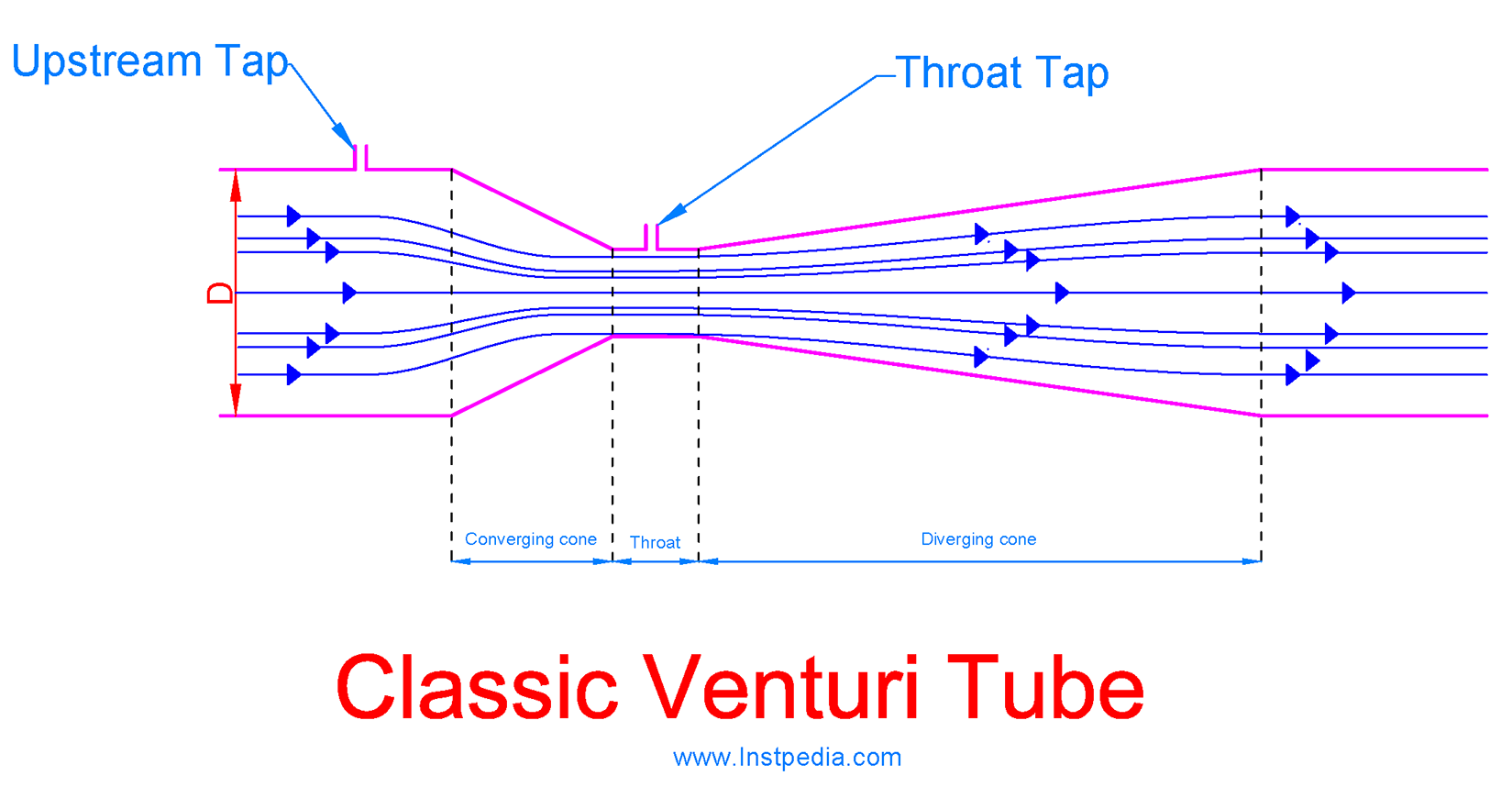
It is recommended to use classic venturi tube for clean gases and liquids, because it is very difficult to clean the taps entry from dirt or sediment.
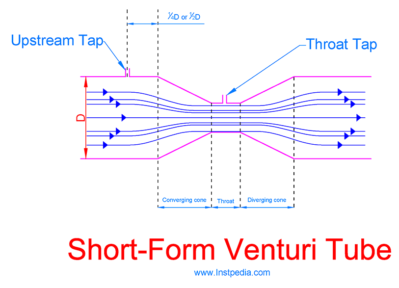
Short-Form Venturi Tube
Because of long converging and diverging runs, classic venturi tube is very expensive for large pipe lines.
Therefore short-form venturi tube was designed by manufacturers with lower cost.
In short-form venturi tube, converging and diverging cones angle increased from 7 to 21 degrees in order to shorten the length.
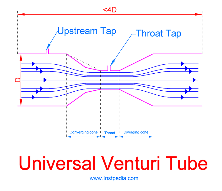
Universal Venturi Tube
Universal venturi tube is designed to improve classic venturi tube pressure recovery better and reduce cost.
The converging and diverging lays are shorter, however straight pipe run at upstream for conditioning the flow profile should be considered.
Converging cone internal diameter reduces with two angles, but the whole construction is identical to classic venturi tube.
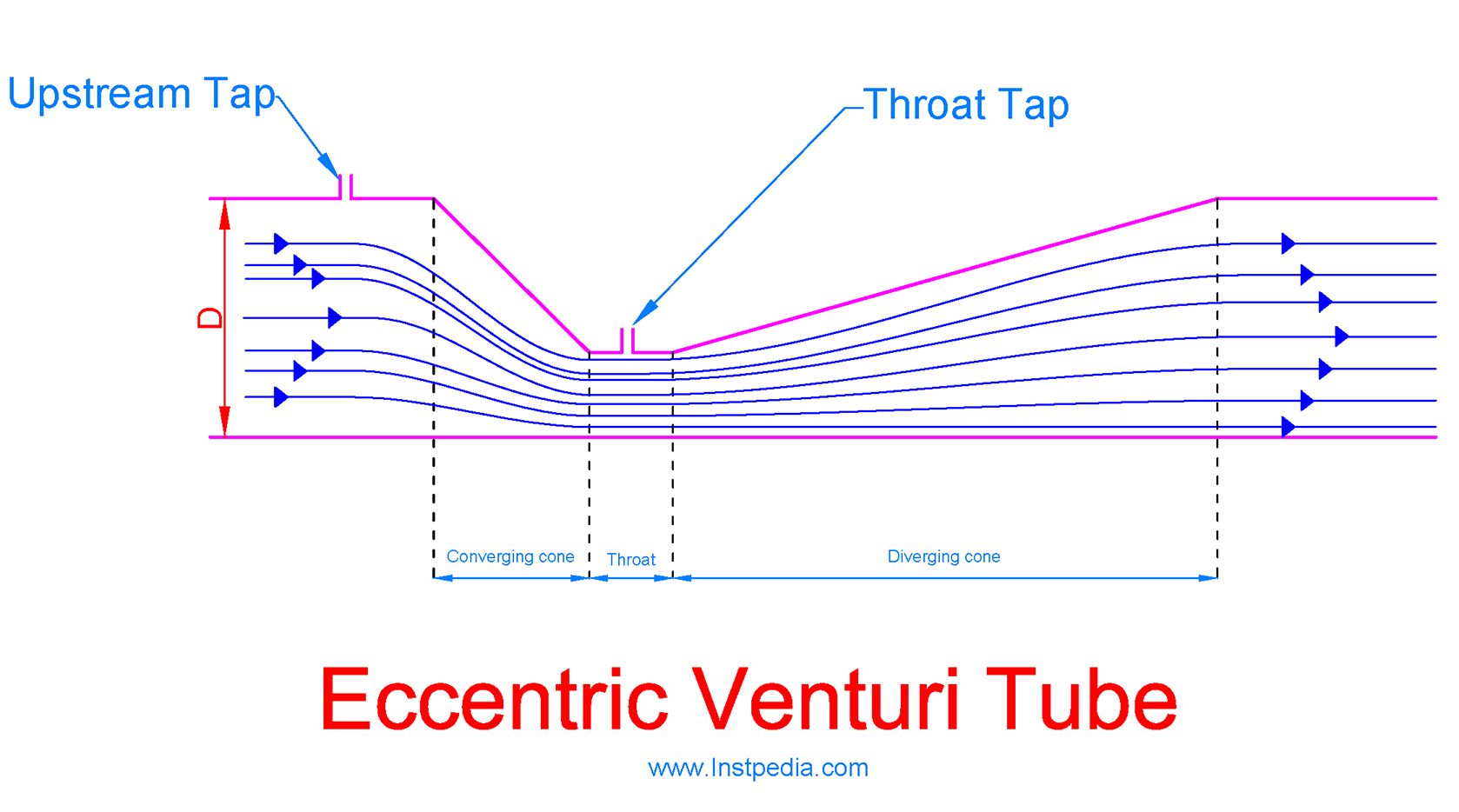
Eccentric Venturi Tube
Eccentric venturi tube is the same as classic venturi tube, however the throat center has an offset from the pipe center line.
Eccentric venturi tube is usually used for multi- phase or heavy slurry services.
Eccentric venturi tube can be rectangular instead of cylindrical, for rectangular duct systems.
Venturi Tube Accuracy
If the venturi tube accuracy is about 0.75% of span.
It is obvious that DP transmitter's accuracy of 0.1% of span should be added to the mentioned above accuracy, in order to obtain the whole flowmeter set accuracy.
Venturi Tube Rangeability
Rangeability or turndown ratio is the ratio of maximum to minimum measurable flow rate with the defined accuracy.
Rangeability for venturi tubes, similar to orifice plate, is 3:1.
It means that if the minimum measuring flow rate is 20 m3/h and the accuracy is 0.85% of span, then the maximum flow that could be measured with accuracy of 0.85% is 20 x 3= 60 m3/h.
Flow Nozzle
Flow nozzle is a flow element which is installed between flanges similar to orifice plate, but can pass about 60% more flow than orifice plate.
Flow nozzle provides the differential pressure for flow measurement with a smooth convergent section.
Flow nozzles are difficult to fabricate and have limitation with viscous liquids, therefore they are not often used for usual flow measurement because venturi tubes have better performance.
Flow nozzles are usually used for high Reynolds Number or high flowrate of superheated steam services as differential pressure flowmeter.
Flow nozzles are also used for critical flow measurement of gas services.
In this conditions they are not differential pressure flowmeter and they use gas sonic flow conditions at the throat to measure mass flow.
In critical flowmeters which are using flow nozzle, sonic conditions are achieved at the nozzle throat, so the velocity is maximum.
Therefore the mass passing through the throat is a function of inlet density, which can be determined from inlet pressure and other gas physical properties.
ASME PTC 19.5 section 8 and ISO 9300, provide sizing and use of flow nozzles in critical flow measurement.
EN ISO 5167-part 3 provides the information for flow nozzle dimension and sizing for differential pressure flow measurement.
There are three types of flow nozzles:
- ISA 1932
- Long Radius (ASME)
- Venturi Nozzle
ISA 1932 Nozzle
ISA 1932 Nozzle is a European design, consists of three parts; convergent section, rounded profile and cylindrical throat.
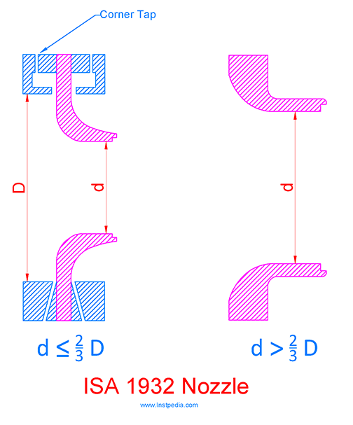
Upstream tapping shall be corner type.
Downstream tapping could be corner tapping, flange tapping or pipe tapping.
According to EN ISO 5167-part 3, the ISA 1932 Nozzle shall be used when:
- 50mm ≤ D ≤ 500mm
- 0.3 ≤ β ≤ 0.8
Long Radius (ASME) Nozzle
Long Radius (ASME) Nozzle is an American design, consists of convergent inlet in shape of a quarter ellipse and a cylindrical throat.
There are two types of long radius nozzle, based on required β ratio:
- High-Ratio Nozzle ( 0.25 ≤ β ≤ 0.8 )
- Low-Ratio Nozzle ( 0.20 ≤ β ≤ 0.5 )
High-Ratio Nozzle has a flattening convergent section.
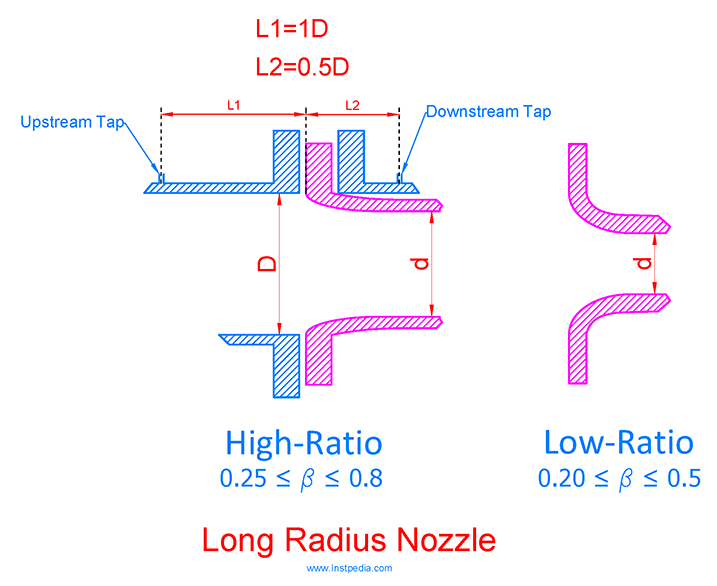
The centerline of upstream tapping shall be at 1D from the inlet face of the nozzle.
The centerline of downstream tapping shall be at 0.5D from the inlet face of the nozzle except in case of Low-Ratio Nozzle with β <0.3188 for which it shall be 1.6d.
According to EN ISO 5167-part 3, the Long Radius Nozzle shall be used when:
- 50mm ≤ D ≤ 630mm
- 0.2 ≤ β ≤ 0.8
- 104 ≤ Reynolds Number ≤ 107
- Pipe relative roughness ≤ 3.2 x 10⁻⁴ (in upstream)
Venturi Nozzle
Venturi nozzle is an average design between ISA and ASME flow nozzles.
It consists of a convergent section, cylindrical throat and a divergent section.
The upstream face is identical with ISA 1932 Nozzle face.
Upstream tapping shall be corner tapping, but the downstream tapping could be throat tapping with at least four single pressure tapping leading into an annular chamber, piezometer ring or triple-T arrangement (referring to EN ISO 5167).
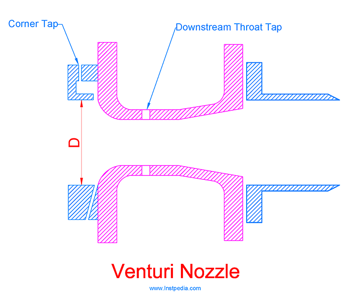
According to EN ISO 5167-part 3, the Venturi Nozzle shall be used when:
- 65 mm ≤ D ≤ 500 mm
- d ≥ 50 mm
- 0.316 ≤ β ≤ 0.775
- 1.5 x 10⁵ ≤ Reynolds Number ≤ 2 x 10⁶
Flow Nozzle Accuracy
Flow Nozzle accuracy is about 1% of span.
It is obvious that DP transmitter's accuracy of 0.1% of span should be added to obtain the whole flowmeter set accuracy.
Flow Nozzle Rangeability
Rangeability or turndown ratio is the ratio of maximum to minimum measurable flow rate with the defined accuracy.
Rangeability for Flow Nozzle, similar to orifice plate, is 3:1.
Segmental Wedge Flowmeter
Segmental Wedge Flowmeter provides the differential pressure for flow measurement by a v-shaped wedge.
Segmental Wedge Flowmeter can be used for very difficult fluid services such as, very high viscosity, very low velocity, corrosive, high temperature, slurries, heavy oil, dirty, containing solid particles, cement and asphalt services.
The main advantage of segmental wedge flowmeter is that it can operate in services with Reynolds Number of 500 to 1000.
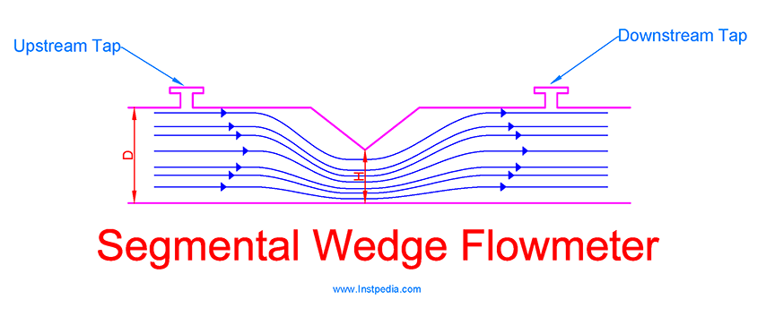
Ratio of H/D is similar to β ratio in orifice plates, which determines wedge dimension, flow scale and differential pressure range.
For clean services regular threaded tapping could be suitable, but in most of Segmental Wedge Flowmeter applications, diaphragm seal connection should be uses to protect the transmitter sensor.
Segmental Wedge Flowmeter does not require any special maintenance, which covers its high initial cost.
Segmental Wedge Accuracy
Segmental Wedge Flowmeter accuracy is about 2% to 5% of span, but if it is calibrated, accuracy could reach 0.75% of span.
It is obvious that DP transmitter's accuracy of 0.1% of span should be added to obtain the whole flowmeter set accuracy.
Segmental Wedge Rangeability
Rangeability or turndown ratio is the ratio of maximum to minimum measurable flow rate with the defined accuracy.
Rangeability for Segmental Wedge Flowmeter, similar to other differential pressure flowmeters, is 3:1.
V-Cone Flowmeter
V-Cone flowmeter (Venturi- Cone) is a differential pressure flowmeter consist of a cone in centerline of pipe.
The cone reduces the cross-sectional area and provides differential pressure for flow measurement.
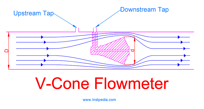
V-Cone flattens the velocity profile, therefore it is insensitive to flow distortions and swirls.
This develop in velocity profile results a true square root relation of DP and Flow rate that optimizes the accuracy.
Because of cone geometry V-Cone Flowmeter is suitable for high velocity, erosive or corrosive services.
It has a better performance in low Reynolds Number services and requires less upstream straight pipe than orifice plates.
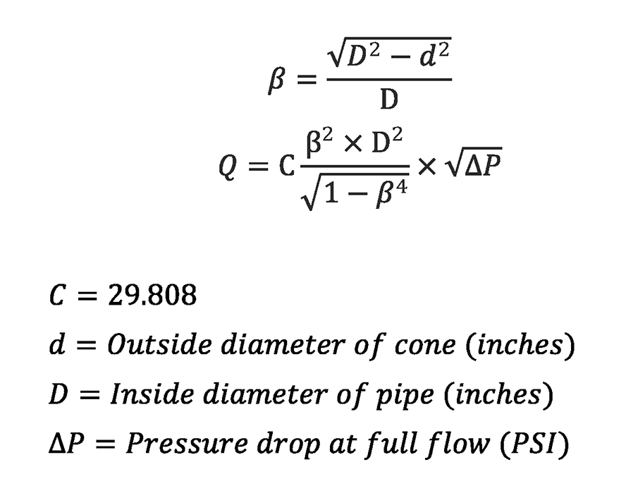
β ratio and flow can be calculated using the following equations:
V-Cone Flowmeter Accuracy
V-Cone Flowmeter accuracy is about 1% of span, but if two DP transmitters are used (one calibrated for low flow rates and the other one calibrated for high flow rates), then the accuracy could be optimized to 0.25% of span.
V-Cone Flowmeter Rangeability
Rangeability or turndown ratio is the ratio of maximum to minimum measurable flow rate with the defined accuracy.
Rangeability for V-Cone Flowmeter, similar to other differential pressure flowmeters, is 3:1.
Pitot Tube
In 1732, Henri Pitot, a French hydraulic engineer, invented the Pitot tube.
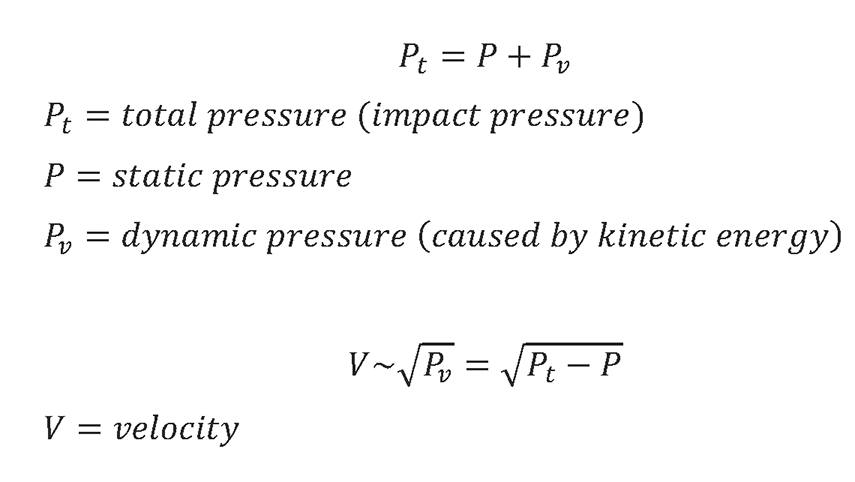
Henri Pitot, discovered that the velocity of a fluid is proportional to square root of dynamic pressure, which is caused by kinetic energy of the fluid.
Impact pressure (total pressure) on an object in a fluid is the sum of static pressure and dynamic pressure.
Basic Pitot Tube measures the Impact pressure and static pressure, and derives dynamic pressure using a differential pressure transmitter.
Then calculates fluid velocity from dynamic pressure and finally computes flow rate from velocity.
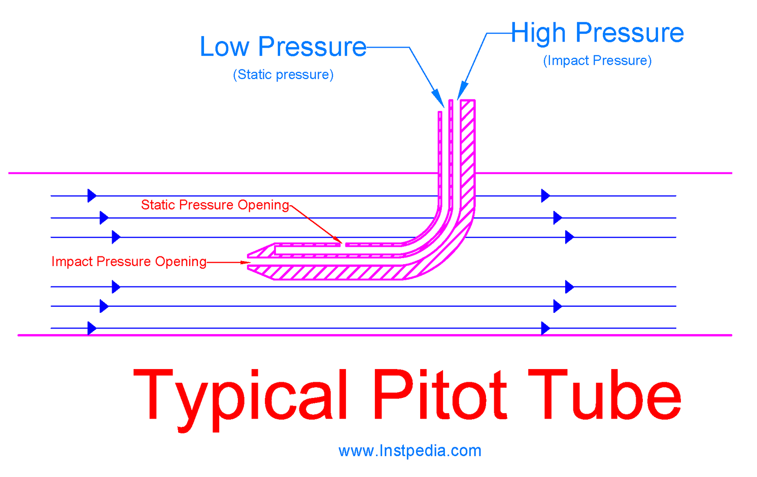
The above figure shows a typical Pitot Tube that measures total pressure and static pressure from center line of the pipe and velocity profile.
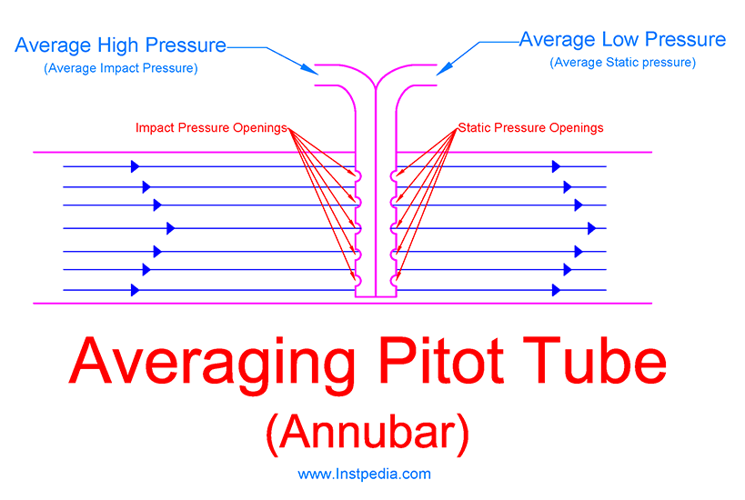
In order to achieve true measurement of flow, it is essential to measure an average value of velocity.
Averaging Pitot Tube (Annubar), measures total pressure and static pressure from different points of flow velocity profile and provides and average velocity.
It consists of two flow tubes, one for impact pressure and the other one for static pressure measurements with several distributed pressure openings along each tube, to obtain average pressure from different points of velocity profile.
Pitot Tube Applications
Pitot Tube is simple, inexpensive and has a very low permanent pressure loss, but has the disadvantage of low accuracy and low rangeability.
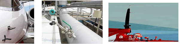
It is appropriate for large pipes or ducts flow measurement, while other flowmeters are very expensive.
It is used in airplanes and racing cars to measure air speed.
Pitot Tube is suitable for low or medium flow gas services where its low accuracy is acceptable.
Another disadvantage Pitot Tube is that it should be used only for clean liquids and gases, because dirty, sticky and containing solid particle services may plug the pressure openings.
Pitot Tube Installation
Upstream and downstream straight run for Pitot Tubes is necessary to have the optimum accuracy.
Pitot tubes installation could be permanently with threaded or flanged connection or could be hot-tap using retractable probe facilities through an isolating valve.
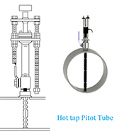
Hot tap installation provides the ability to remove the Pitot Tube without shutting down the process or isolating the pipe line.
As the medium in the pipeline passes by the Pitot Tube, it forms a turbulent wake (Von Karman trail), that generates a vibration in the Pitot Tube, proportionate to the diameter of the tube and velocity of the medium and may cause the Pitot Tube failure.
Therefore manufacturer shall calculate the minimum and maximum fluid's velocity limitations and shall design Pitot Tube diameter in a way that guarantees Pitot Tube safe operation.
Pitot Tube Accuracy
Pitot Tube accuracy is from 0.5% to 5% of full scale, depending on calibration and pitot tube type.
It is obvious that DP transmitter's accuracy of 0.1% of span should be added to obtain the whole flowmeter set, accuracy.
Pitot Tube Rangeability
Rangeability or turndown ratio is the ratio of maximum to minimum measurable flow rate with the defined accuracy.
Rangeability for Segmental Wedge Flowmeter, similar to other differential pressure flowmeters, is 3:1.
Variable Area Flowmeter (Rotameter)
In 1909, Deutsche Rotawerke GmbH, a German company developed the Karl Kueppers's invented Variable Area Flowmeter which had a rotating float with the brand of Rotameter.
Very soon Rotameter became a synonym for Variable Area Flowmeters.
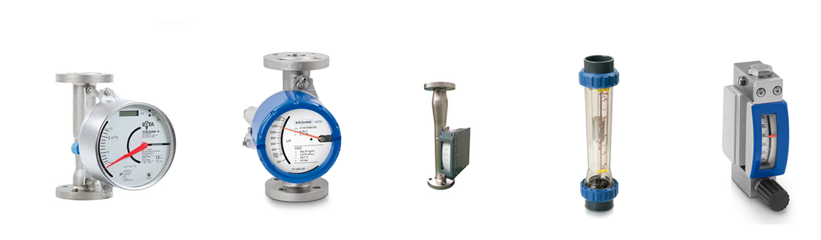
Variable area flowmeter consists of a vertical tapered tube with a float inside of it.
Density of float should be greater than the fluid density it means that it should be very heavy that if the tube is full of fluid without velocity (without flow) the buoyancy force could not be sufficient to rise the float.
In gas services buoyancy is negligible.
Float rises in the tube by flow velocity force (drag force) and stops in a stable position, where velocity head, buoyancy, gravity and friction forces are balanced.
At this dynamic equilibrium point, flow is proportional to the area between the float and the tapered tube which will be indicated in a scaled indicator beside the tube.
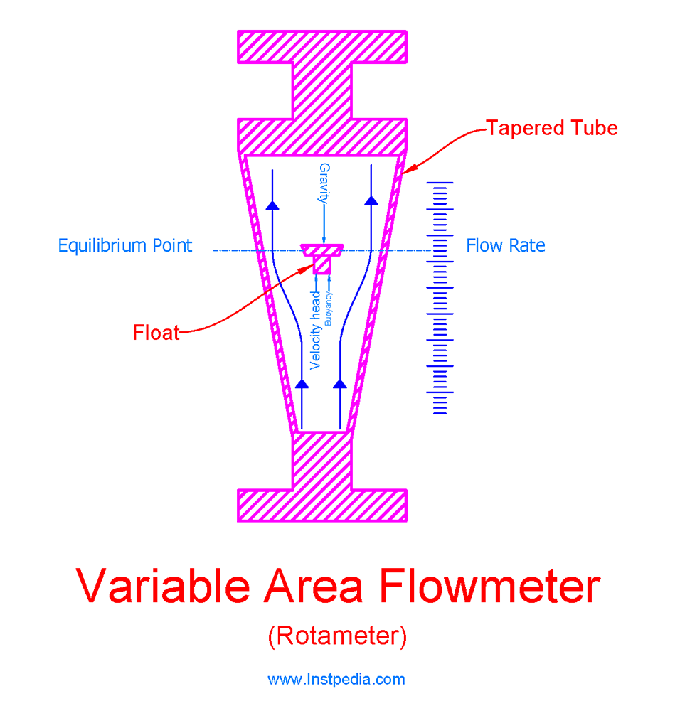
As the float rises, the annular area between float and tapered tube increases and the differential pressure across the float decreases, hence if the float wants to go higher more velocity head force (higher flow rate) is required.
The greater the flow rate, the higher the float rises.
Rotameter is an inexpensive flowmeter, so it is widely used in industries mostly as local flow indicators and in some cases as flow transmitter or flow switch.
Glass tube rotameters are not suitable for industrial applications, because of pressure and temperature limitations of glass and probability of glass failure during operation and maintenance of the plant.
Metal tube rotameters are preferred in outdoor industrial applications.
Metal tube material should be a non-ferrous stainless steel that could be able to pass the magnetic field of the magnet float inside of tube to the outside indication scale in order to move the indicator pointer with float movement (magnetic coupling).
High temperature may affect magnetic materials in float construction and attenuate its magnetic field, hence the operating temperature range which is specified by manufacturer should be taken into consideration.
Plastic tube rotameter is available for corrosive services, but if it meets design pressure and temperature of the pipe line.
Upstream piping configuration does not affect rotameter accuracy, therefore upstream straight run is not required.
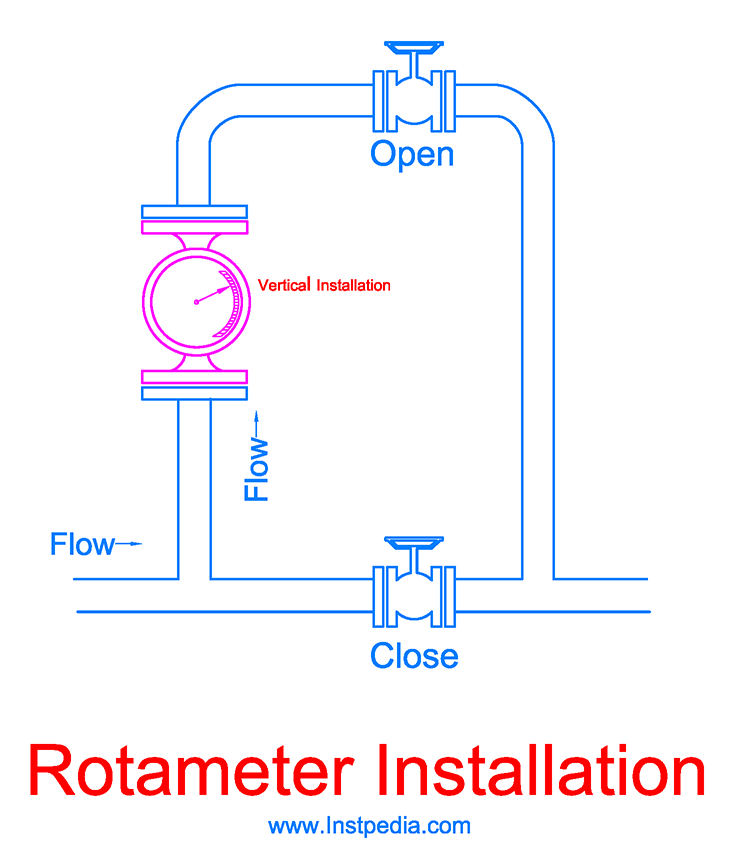
Variable Area Flowmeter Installation
Variable Area Flowmeter (Rotameter) must be installed vertically and the flow must enter from bottom, because gravity has an essential role in this flowmeter.
There is a type of variable area flowmeter consists of a cylinder instead of tapered tube and a piston instead of float and a spring plays the role of gravity.
This Piston flowmeter can be installed horizontally.
The spring and piston may require calibration and maintenance after continues operation.
Care should be taken not to install Metal Tube Rotameters near equipment that have strong magnetic field around them, like power transformers or medium voltage motors, because strong magnetic field may affect the magnetic characteristic of the float.
Variable Area Flowmeter Sizing
Calculation sheet should be provided individually for each Variable Area Flowmeter (Rotameter) by manufacturer in such a way that process maximum flow rate should be maintained at 90% to 95% of maximum rate of rotameter scale.
Calculation aim is to achieve rotameter size with the best accuracy and minimum pressure drop.
Rotameter size could be the same as pipe size or less.
Mostly, calculation result is a rotameter with smaller size than pipe size in order to maintain the accuracy.
As the rotameter size decreases, the pressure drop increases.
The important point of calculation is to select a size with a pressure drop less than Maximum Allowable Pressure Drop, which is specified in rotameter datasheet by process department.
VDI VDE 3513-1 standard provides calculation methods for Variable Area Flowmeters.
Variable Area Flowmeter Material
Glass tube rotameters are not suitable for most of industrial applications, due to their pressure and temperature limitations and probability of glass failure.
Metal tube rotameters are preferred.
In metal tube rotameters mostly float and tube materials are the same.
AISI 316 / 316L / 316Ti Stainless Steels could be the best and the most common material for tube, float and any wetted part material due to proper resistance against corrosive services and acceptable mechanical properties with temperature range of -254 to 816°C.
Also AISI 316 / 316L / 316Ti are non-ferrous stainless steels that could pass the float magnetic field to the outside indicator pointer which is essential for rotameter operation.
For services that contain an aggressive species such as chloride (Cl-), like seawater, Austenitic Stainless Steels (316SS, 304SS, 321SS …) are not applicable.
Alloys that have PREN (Pitting Resistance Equivalent Number) greater than 40 are recommended for such services.
Nickle based alloys such as Monel and Inconel, including Hastelloy which has high chromium and molybdenum contents are the best material selection for seawater and chloride containing services, but the cost is considerable.
Variable Area Flowmeter Accuracy
Variable Area Flowmeter (Rotameter) accuracy is 1 to 10 % of full scale.
Some manufacturers express rotameter accuracy in accordance with the method described in VDI/VDE 3513 standard.
For example: G=4% (qG= 50 %)
G is a constant error in percent of actual flow above qG.
qG is the value in percent of full scale (generally 50%).
G=4% (qG = 50 %), means that the constant error for flow rates from 50% up to 100% of rotameter scale is 4%.
Variable Area Flowmeter accuracy is not acceptable for a precision control loop, hence Variable Area Flowmeter with 4~20 mA output signal could be used just for flow indication in control system in addition to local flow indication.
With the same reason Variable Area Flowmeter using a contact switch for a Digital Output Signal, is not recommended as a flow switch for important process control logics.
The most reliable application for rotameters is local flow indication for operators in the field.
Variable Area Flowmeter Rangeability
Rangeability or turndown ratio is the ratio of maximum to minimum measurable flow rate with the defined accuracy.
Rangeability for Variable Area Flowmeter (Rotameter) is 10:1.
Variable Area Flowmeter Advantages
- Inexpensive
- Simplicity
- High rangeability 10:1
- Low permanent pressure loss
- Insensitive to viscosity
- Not affected by upstream piping configuration
- No necessary maintenance is required
Variable Area Flowmeter Limitations
- Low Accuracy
- Must be installed vertical (except Piston Type)
- Accumulation of fluid's ferromagnetic particles on the float
Mass Flowmeters
In most of industrial processes mass flowrate is required for precision process control, however most of flowmeters measure volumetric flow rate, which needs to be multiplied by fluid density to be converted to mass flow rate.
Density changes with temperature and pressure changes, which leads to inaccurate mass flow calculation.
This density change could be negligible for liquids, but for gases it is considerable.
Pressure and temperature compensation (PT Compensation) that justifies density with the measured pressure and temperature at the time with volumetric flow measurement, increases the accuracy, but this could add the inaccuracy of pressure and temperature measurement devices to the system.
Mass flowmeters solve this problem by direct measurment of mass flowrate.
Mass Flowmeters Types
The most common mass flowmeters in different industries are:
- Coriolis flowmeter
- Thermal mass flowmeter
- Radiation flowmeter
There are other mass flowmeter types, such as Angular Momentum, Gyroscopic, etc…, but they are seldom used in today's industries.
Coriolis Flowmeters
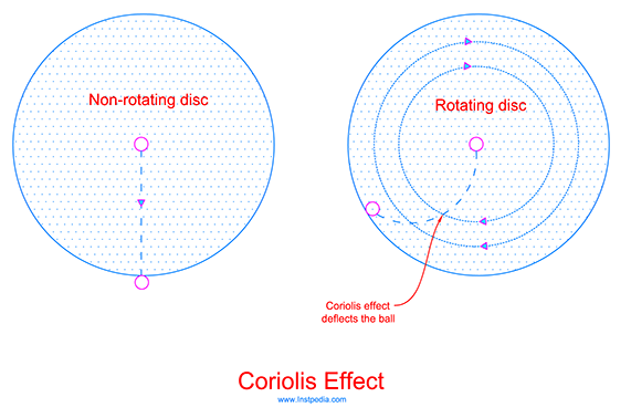
Coriolis flowmeter works based on Coriolis Effect.
In 1835, a French scientist, Gaspard-Gustave de Coriolis, described the inertia force influence in Newton's Law of Motion of objects in a rotating frame of reference, in a paper, which is called Coriolis Effect.
If we toss a ball from center point of a non-rotating disc to another person at opposite point outside the disc, the ball moves in a straight line and that person can catch it.
But if we toss the ball while the disc is rotating, then Coriolis force and centrifugal force appear and deflect the ball in a curved path to another point.
This is the Coriolis Effect.
Our planet, Earth, rotates about its own axis, hence it is a rotating sphere.
Every object on Earth, when moving, is deflected because of Coriolis Effect.
It does not matter in what direction the object is moving.
Coriolis Effect always seeks to bring an object back to its initial position by constantly deviating it perpendicularly to its direction of movement.
Trains are affected by Coriolis Effect and tend to put more pressure on one of the rails, which could cause abrasion on one side of the railway.
Coriolis Effect plays a huge role in weather systems movement over the Earth.
Coriolis Effect deflects the moving objects to the right in the Northern Hemisphere and deflects them to the left in the Southern Hemisphere.
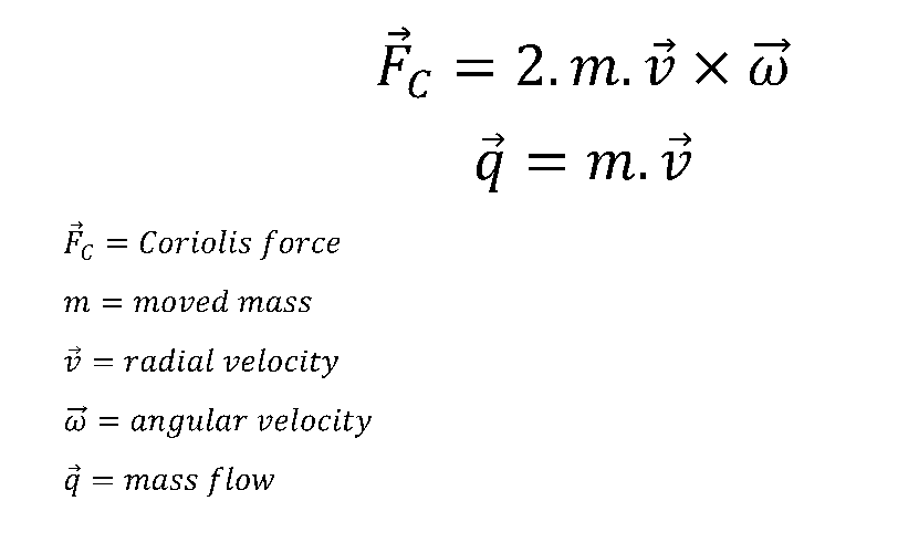
Coriolis flowmeter drives mass flow rate from Coriolis force measurement which has a direct relation to the moving mass and its radial and angular velocities.
Coriolis Flowmeters Working Principle
Coriolis flowmeter is consist of two flow tube with the same diameter and size parallel from flow meter input to its out.
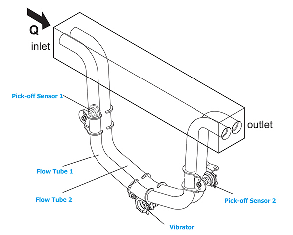
There is a vibrator at middle of the tubes that oscillates tubes with a specific frequency.
Tubes oscillation is detected by two magnetic pick-off sensors, which are installed at two side of the tubes.
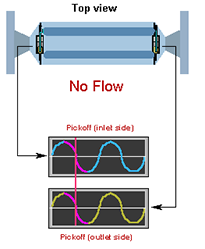
During a no flow condition, the detected oscillating frequency by sensor 1 and 2 are the same and equal to the vibrator frequency.
In this condition (no flow) the output signals of sensors are two sine waves which are in phase with each other.
When the fluid moves into the flow tubes, Coriolis forces appear and do not let the two sides of flow tubes to oscillate with vibrator frequency and cause the flow tubes to twist in opposition to each other.
In this condition the output signals of sensors are two sine waves which are not in phase with each other and there is a time difference between the sine waves.
This time difference (ΔT) is directly proportional to the mass flow rate.
Coriolis Flowmeter Material
Flow tubes wall thickness should be as thick as possible, in order to avoid decreasing the instrument sensitivity to Coriolis Forces.
Therefore special care should be taken for tubes material selection considering corrosion, erosion and pressure rating of process media.
Process temperature also, has a major role in construction and material selection of flow tubes because of tubes thermal expansion.
High process temperature causes tubes to expand while the supports and housing at two sides of the tubes expand less due to large temperature difference, which increase the axial force of the tubes.
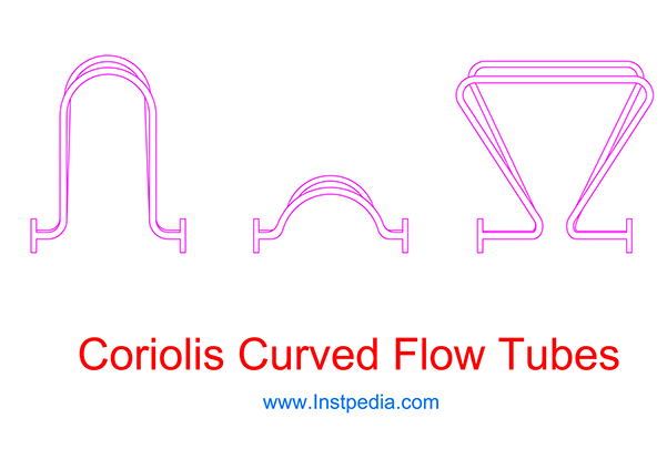
Hence stainless steel tubes that have high thermal expansion, need to have a curved shape to reduce the axial stress.
For straight tubes, using material with small thermal expansion such as titanium or zirconium may solve the axial stress problem.
AISI 316 / 316L / 316Ti Stainless Steels is the common material for flow tubes and any wetted part with temperature range of -254 to 816°C.
For services that contain an aggressive species such as chloride (Cl-), like seawater, Nickle based alloys (Inconel, Hastelloy…) that have PREN (Pitting Resistance Equivalent Number) greater than 40 are recommended.
Coriolis Flowmeter Accuracy
Coriolis flowmeter is the most accurate flowmeter.
Its accuracy considering different manufacturers could be:
- 0.05% ~ 0.15% of full scale for liquids
- 0.25% ~ 0.5% of full scale for gases
- 0.002 g/cm3 ~ 0.00025 g/cm3 for liquid density metering
Coriolis Flowmeter Rangeability
Rangeability or turndown ratio is the ratio of maximum to minimum measurable flow rate with the defined accuracy.
One of the most important advantages of Coriolis flowmeter is high rangeability.
Coriolis Flowmeter rangeability could be 20:1 up to 100:1.
Coriolis Flowmeter Advantages
- Measuring mass flow directly
- Very high accuracy
- Very high rangeability
- Insensitive to flow and velocity profile (no requirement for downstream and upstream straight pipe run.)
- No Reynolds Number limitation
- Can be used for fluctuating flows
- Measuring forward or revers flows
- No requirement for routine maintenance
Coriolis Flowmeter Limitations
- High price
- Not available for large pipes
- Not suitable for low pressure gases (Thermal mass flowmeter is recommended for these applications.)
- Sensitive to pipe vibration (Have been solved by some manufacturers.)
- Not suitable for high temperature services
- Not recommended for polymerizing services
Coriolis Flowmeter Applications
Coriolis flowmeter can be used in most of services for flow measuring liquids, gases or slurries.
Coriolis flowmeters are used when:
- Mass flow measuring is needed
- High accuracy is necessary
- High rangeability is required
- Density measurement is desired
- Custody transfer / Fiscal metering
- There is no sufficient space for straight run downstream of flowmeter
Coriolis Flowmeter Sizing
As mentioned before Coriolis flowmeters have an extreme rangeability or turndown ratio, therefore during the sizing two or more sizes of meter could be able to cover the required flow range.
The difference between these sizes are the pressure drop and accuracy in low flows.
Downsizing reduces the cost, but increases the velocity, erosion and pressure drop.
Selecting the largest size reduces the pressure drop but increases the uncertainty in low flow rates.
Manufactures use a sizing software that provide a calculation sheet inclusive of a list of different sizes with the relevant values for velocity, pressure drop and accuracy at minimum, operating(normal) and maximum flow rates.
This software is able to calculate occurring of flashing and cavitation for each case.
Finally, proper flowmeter size selection is a conclusion of considering cost, pressure drop, velocity, erosion, corrosion and accuracy.
Coriolis Flowmeter Installation
For liquid services, flow tubes should remain full of fluid.
Liquid and gas mixture should be avoided.
For gas services, flow tubes should be full of gas without any condense or droplet.
Vertical installation with an upward flow direction is the preferred installation, but the horizontal installation is acceptable and very common.
In vertical installation solid particles will remain down in pipe line due to gravity force and will not enter the flow tubes, also gases can scape upward and will not be trapped in flow tubes.
But usually due to piping design limitations, horizontal installation will be considered for Coriolis flowmeters.
For horizontal installation, care should be taken not to install Coriolis flowmeter in high point of system in liquid services to avoid gas accumulation in flowmeter.
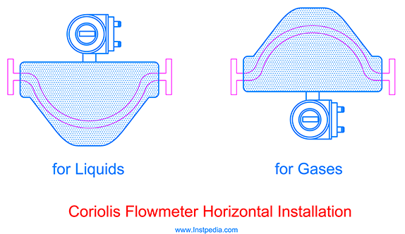
For liquid services, curved flow tubes should be installed downward to avoid gas collection in tubes during no flow condition.
For gas services, curved flow tubes should be installed upward to avoid liquid collection in tubes during no flow condition.
Piping vibration and shocks are not a serious problem for modern Coriolis flowmeters, but they could be harmful for any instruments and sensitive devise, so they should be solved and damped by a good piping support design.
As mentioned formerly, Coriolis flowmeters are not sensitive to flow profile and Reynolds Number, therefore there is no requirement for downstream and upstream straight pipe run.
Thermal Mass Flowmeters
Thermal Mass flowmeters can measure mass flow rate for liquids, gases or slurries directly, but they are most often used for low gas flow measurement.
There are two measuring principles for Thermal Mass Flowmeters:
- Constant Power
- Measures the fluid temperature change as it passes over a heated body with a known amount of heat (constant power).
- Constant Temperature
- Measures the rate of heat loss from a heated body with a kept known temperature (constant temperature) as the fluid passes over it.
Constant temperature measuring principle has a faster response.
Thermal Mass Flowmeter types
The most common thermal mass flowmeter are:
- Heat Transfer
- Heated Tube
- Bypass design
- Hot Wire
Heat Transfer Flowmeter
This flowmeter consists of two temperature sensor downstream and upstream of a heater.
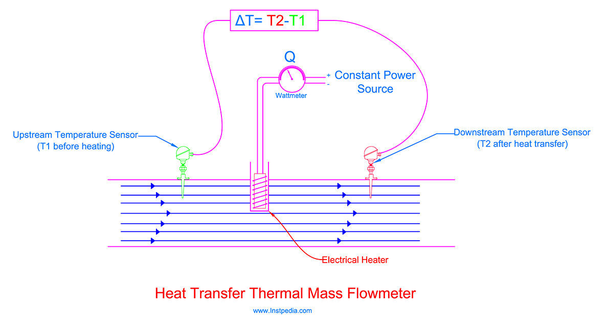
Heat is transferred to the stream by the electrical heater and its amount is equal to the electrical power consumption of the heater.
The upstream temperature sensor provides the stream temperature before transferring the heat and it is the reference temperature.
The downstream temperature sensor provides the heated stream temperature.
Based on heat transfer equation, the temperature rise of the fluid is proportional to the received thermal energy (heat) and fluid mass.
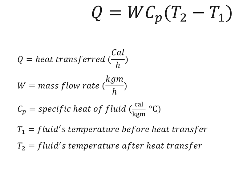
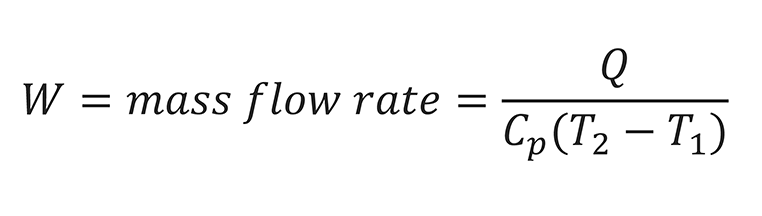
Simply mass flow rate is derived from the following equation:
Heated Tube Flowmeter
In order to protect heater and temperature sensors from corrosion and erosion, heated tube thermal mass flowmeter is design so that the heater and temperature sensors are located outside the pipe.
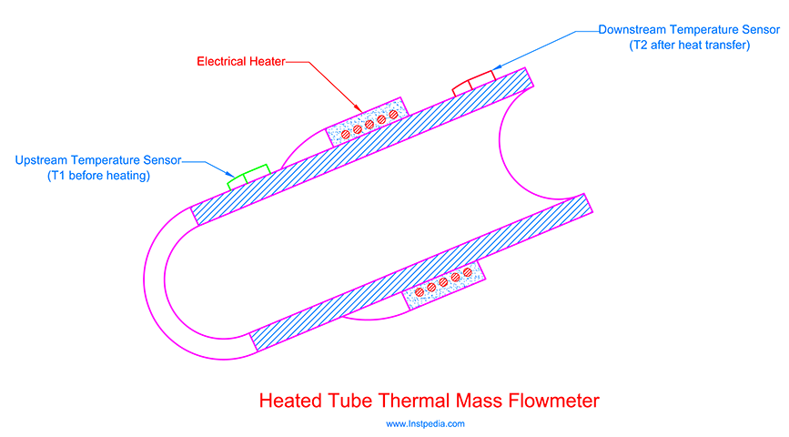
This design complicates the heat transfer to the fluid and its distribution in it, in addition mass flow rate and temperature difference relationship becomes nonlinear.
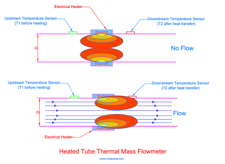
Upstream temperature sensor measures the fluid temperature through the pipe wall, before the heating.
This sensor should be at a distance to the heater that the heat could not be conducted to the sensor by pipe wall.
Downstream temperature sensor should be near the heater to measure pipe wall temperature which is fluid's temperature after heat conduction and it is proportional to mass flow rate.
In this flowmeter, mass flow rate and temperature difference relationship is nonlinear.
Both constant power and constant temperature measuring modes, which are described before, are available for this flowmeter.
Bypass Type Flowmeter
Bypass thermal mass flowmeter is another type of Heat Transfer Flowmeter.
It consists of a bypass line on the main line, which is a very thin capillary tube with heater and two temperature sensors.
For high flow rates measurement, a restriction device is required to facilitate flow through the bypass tube.
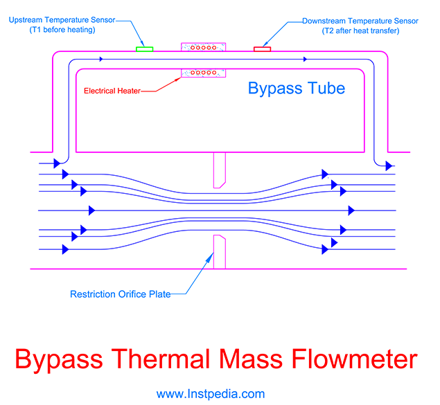
Flow measuring principle is the same as described for Heat Transfer Flowmeters.
The bypass line flow needs to be laminar, hence in some models a laminar flow device is considered in the main tube to provide laminar flow in the bypass tube and also to play the role of restriction device.
Hot Wire Flowmeter
This flowmeter consists of two temperature sensor which are in a Wheatstone bridge.
One of the temperature sensors measures the gas temperature as a reference temperature.
The other sensor is continuously electrically heated and as the flow begins the heat is carried off by the flow.
The temperature difference between the two temperature sensors is set to be constant (Constant temperature principle).
As the flow cools the heated sensor, the Wheatstone bridge exceeds the heater current in order to maintain the set constant difference temperature between the two sensors.
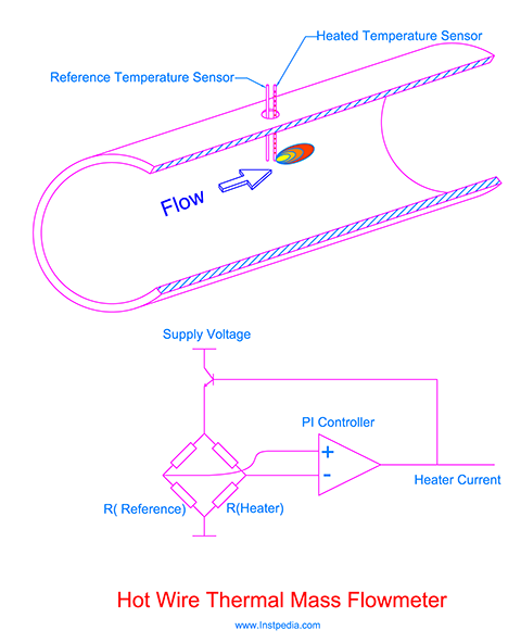
This current change is proportional to the mass flow rate.
Increase of mass flow increases the cooling effect and the temperature difference that causes increase of heater current.
Thermal Mass Flowmeter Accuracy
Thermal mass flowmeter accuracy is 1~2% of full scale.
Thermal Mass Flowmeter Rangeability
Rangeability or turndown ratio is the ratio of maximum to minimum measurable flow rate with the defined accuracy.
Thermal mass flowmeter rangeability could be 10:1 up to 100:1.
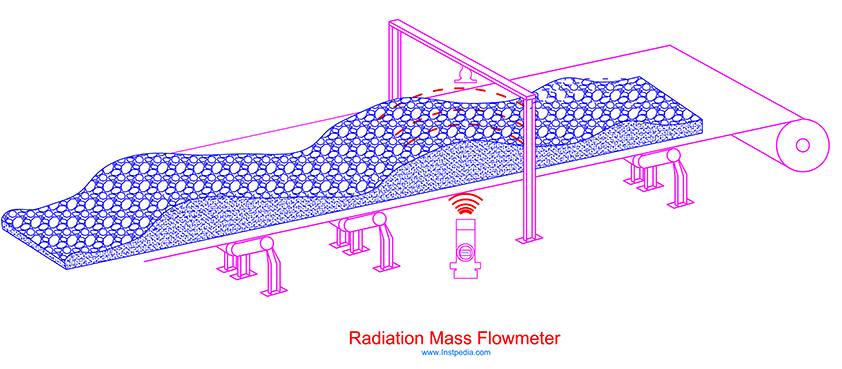
Radiation Mass Flowmeter
Radiation Mass Flowmeter consists of two measuring parts.
The first part measures the density using gamma ray and the other part measures volumetric flow then a flow computer uses these two measuring inputs and provides mass flow rate.
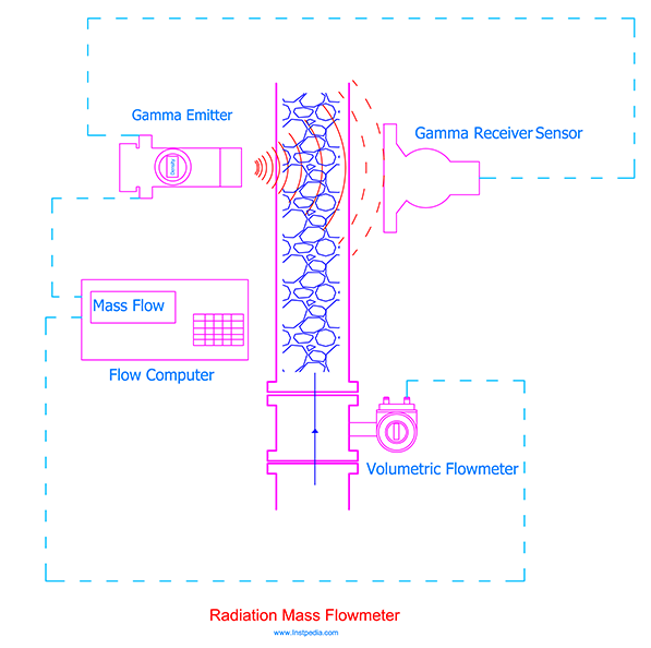
Density meter part have a gamma ray source that emits focused gamma rays from radionuclides such as Cobalt-60 isotope to a receiver sensor.
Receiver sensor convert the quantity and intensity of the received rays into signal that represents the density.
This type of meter is usually used for difficult fluids such as slurries in mineral processing units for density measurement which has a major role in concentration recycling.
In this conditions non-contact measurement is an advantage of this meter.
Radiation mass flowmeter is also used in material handling section of mining industry for mass flow measurements of solids on conveyors.
Volumetric Flowmeters
Volumetric flowmeters mostly measure the velocity of fluid which is proportional to its volumetric flow rate.
Others have a mechanical design that pass over a specific volume of the fluid with each movement, so the number of movements in a specific period of time leads to volumetric flow rate of the fluid.
The most common volumetric flowmeters are:
- Magnetic
- Ultrasonic
- Turbine
- Vortex
- Swirl
- Positive Displacement
- Target
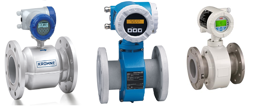
Magnetic Flowmeter
Magnetic flowmeter operation is based on Faraday's law.
Faraday's Law
Faraday’s law states that, when a conductor with a specific length in a closed electrical circuit moves through a magnetic field of a given flux density, a voltage is produced across the two heads of the conductor and can be expressed by the following equation:
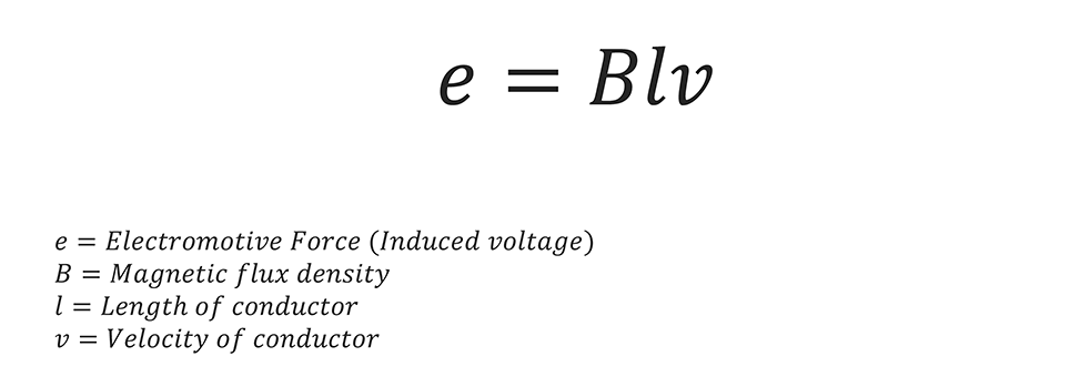
Direction of conductor movement, magnetic field and the electromotive force are all perpendicular to each other.
Magnetic flowmeter uses Faraday's law to measure volumetric flow rate of electrically conductive liquids.
It consists of a non-magnetic pipe (flow tube), a pair of electrodes which are in contact with electrically conductive fluid and a pair of magnetic coils outside the pipe to provide magnetic flied along the flow tube.
As the fluid that has the role of conductor, flows through the provided magnetic field, a voltage is induced across the electrodes.
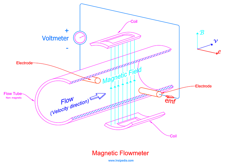
Since the average velocity of the fluid is proportional to its flow rate, by measuring the induced voltage (emf), volumetric flow rate can be derived as the following:
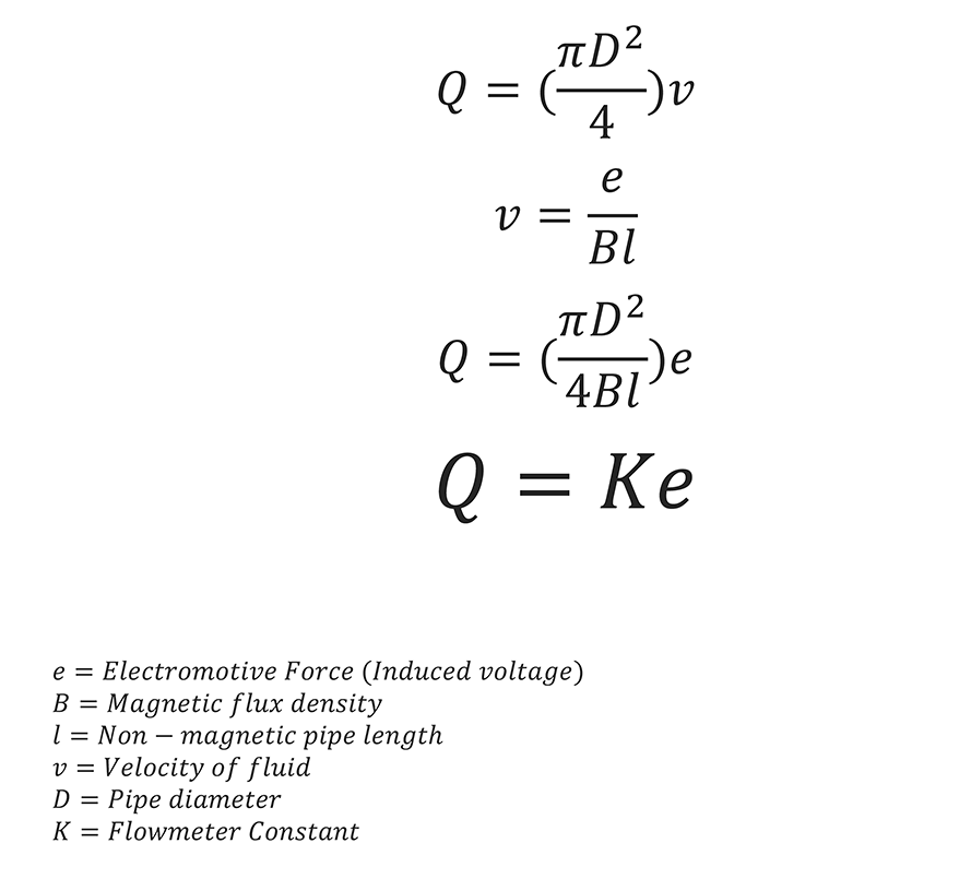
According to the above equation there is a proportional linear relationship between flow rate and induced voltage.
Increase in flow rate results an increase in the generated voltage.
As mentioned before the fluid plays the role of conductor in flow measurement based on Faraday’s law, hence this flowmeter is suitable only for fluids that are electrically conductive and it is not applicable for hydrocarbons or organics.
Fluid minimum required conductivity is 5 µS/cm (Micro-Siemens per Centimeter).
For some fluids such as demineralized water more conductivity about 20 µS/cm is required.
Loop powered magnetic flowmeters (without external power) are available that can be use in intrinsically safe systems.
In this intrinsically safe flowmeter the magnetic field is provided with a very low electrical power, therefore the minimum fluid's conductivity for this meter is 50 µS/cm.
Magnetic Flowmeter Types
The magnetic flowmeter is categorized by coils excitation that produce magnetic field.
The first type is AC excitation that uses AC voltage to generate magnetic field.
AC excitation type is less affected by flow profile, but it requires periodic zero output adjustment at zero velocity because of the induced noise in measuring circuit by the powerful AC magnetic field.
Also the magnetic field varies due to voltage fluctuation or frequency variation which can affect the accuracy.
Magnetic flowmeter developed to DC excitation that does not require zero adjustment and solved the noise problem.
In this design magnetic field coils are periodically energized by DC pulses.
The induced voltage is measured, once when coils are energized and again when coils are not energized.
The measured induced voltage when the coils are not energized is all noise.
Now by subtracting the noise from energized coils measurement, the pure signal could be achieved.
Disadvantage of DC excitation type is low speed response and noise of low conductivity fluids.
Dual-Frequency excitation magnetic flowmeter was designed as an optimized method that have advantages of both AC and DC excitation types and eliminates their limitations.
It uses a compound wave current for coils excitation.
The compound wave consist of a high frequency wave, superimposed on a low frequency wave as the following:
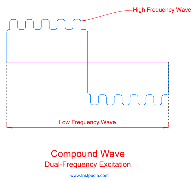
With this method Dual-Frequency excitation, magnetic flowmeter have high speed response, good noise elimination and zero velocity stability and it is good for low conductivity fluids.
Magnetic Flowmeter Accuracy
Magnetic flowmeter accuracy is 0.15 to 0.5 % of full scale.
Magnetic Flowmeter Rangeability
Rangeability or turndown ratio is the ratio of maximum to minimum measurable flow rate with the defined accuracy.
Magnetic flowmeter rangeability could be 30:1 up to 100:1.
Some manufacturers have achieved 1000:1 rangeability for high accuracy models for small pipe sizes.
Magnetic Flowmeter Sizing
The most important point for magnetic flowmeter size selection is that fluid's velocity should be in sensor measuring range.
Fluid velocity can be derived from process flow rates and the pipe size.
In manufacturer sizing software, by entering the conductivity, sensor will be selected according to sensitivity and accuracy.
Then the software compares the derived velocity with the sensor range.
If velocity is beyond the velocity range of the sensor, software goes for a meter size larger than pipe size.
If velocity is below the velocity range of the sensor, software selects a meter size smaller than pipe size, which requires pressure drop calculation.
Physical properties of fluid is considered in sensor velocity ranges selection by the software.
For example sensor velocity range for liquids of normal services is different from slurries or abrasive slurries and each manufacturer has its own guide lines for sensor velocity range.
Magnetic Flowmeter Grounding
Flow tube grounding is essential not only for safety reasons but also ensures the meter operation.
Standard metal pipes are low resistant electrical conductors and transformers, motors windings and medium voltage devices in the plant may produce stray currents along pipe lines.
Magnetic flowmeter electrodes are a possible ground path for such stray currents and excessive ground potentials could damage the meter or affect its operation.
Therefore grounding screws are provided on flow tube to be connected to the ground.
Magnetic Flowmeter Self-cleaning
It is very important for meter operation that the electrodes are kept clean and in contact with the conductive fluid.
Any sediment, dirt or deposit shall be removed from magnetic flowmeter electrodes for proper flow measurement.
The outdated cleaning solution is to use withdrawable electrodes that can be removed from the meter for cleaning or replacement without shutting the process down.
The modern solution is ultrasonic self-cleaning system that a high energy ultrasonic wave is induced in each electrode shaft that produces a vibration at the end of electrodes, which removes any dirt or deposit.
Most of the recent magnetic flowmeters have this ultrasonic self-cleaning option.
Magnetic Flowmeter Applications
Magnetic flowmeters are suitable only for fluids that are electrically conductive and are not applicable for hydrocarbons or organics.
Magnetic flowmeters are the first selection for very corrosive applications.
Also they are proper for difficult fluids such as abrasive or erosive slurries.
Usually their size is the same as pipe line, hence in application that low pressure drop is essential they could be a good solution.
Magnetic flowmeters are not affected by fluid's viscosity, Reynolds Number and velocity profile, therefore they are suitable for non-Newtonian fluids such as pulps in paper or food industries.
Magnetic Flowmeter Installation
Magnetic flow meter should always be liquid filled.
For this reason the ideal installation for magnetic flowmeter is vertical with upward flow.
Also if the fluids contains solid particles vertical upward flow could be protect the liner from erosion.
Horizontal installation is very common due to piping and space limitations and it is acceptable since the electrodes axis is not a vertical plane.
Installing the flowmeter in highest point of the pipe, exceeds the risk of vapour or gas accumulation and should be avoided.
Low point installation of flowmeter should be avoided, too, because increases the risk of solids accumulation, otherwise cleaning facilities such as cleaning valve are considered but it is not recommended.
Magnetic flowmeter should not be installed on pump suction side to protect liner from damaging due to vacuum or low pressure condition.
One of the most important advantages of magnetic flowmeter to other flowmeters is that fluid's velocity profile has no effect on its accuracy, but swirl may cause the velocity vector not to be perpendicular to magnetic field.
Therefore manufacturers recommend 5D straight run upstream and 2D straight run downstream of magnetic flowmeter.
Magnetic Flowmeter Advantages
- High accuracy
- Very high rangeability
- Low pressure drop
- No moving part, hence low maintenance
- Bi-directional flow measurement
- Not affected by fluid's viscosity, Reynolds Number and velocity profile
- Available for wide range of pipe sizes
Magnetic Flowmeter Limitations
- Only suitable for conductive fluids, not applicable for hydrocarbons or organics
- Special liner material should be considered for very erosive, vacuum or high temperature conditions
- Minimum required fluid's conductivity for looped powered intrinsically safe flowmeter is 50 µS/cm.
- Not applicable for high temperature services
Magnetic Flowmeter Material
As mentioned before tube should be made of non-magnetic material.
Therefore ferrous metals cannot be used for tube material.
AISI 316 / 316L / 316Ti Stainless Steels could be the best and the most common material for tube material due to proper resistance against corrosive services and acceptable mechanical properties with temperature range of -254 to 816°C.
Austenitic Stainless Steels (316SS, 304SS …) are non-ferrous stainless steels and can pass magnetic field.
It is recommended to consider flow tube as wetted part, despite the fact that liner prevents flow tube to contact the fluid.
For liner material selection, fluid physical and chemical properties in addition to fluid temperature shall be considered.
PTFE (Polytetrafluoroethylene) and PFA (Perfluoroalkoxy alkanes) are the most common materials for liner.
Both have good corrosion resistance properties.
PFA is more flexible but less resistant to heat than PTFE.
Their weakness is abrasion and high operating temperature.
For high operating temperature (more than 200ºC) and abrasive services, ceramic materials like AL2O3 are used for liner material.
Ceramic is very strong and wear resistance material but it is brittle in case of tension or bending and sudden temperature drop.
Ceramic liner is not proper for very aggressive and corrosive services.
Hard rubber materials are available for abrasive and corrosive services for liner material.
It is very important to inform the manufacturer about the gasket material which is in accordance with the project PMS (Piping Material Specification), to be considered in liner material selection.
Electrode material should be non-ferrous stainless steels and could be 316SS, 316L SS, Hastelloy C, Platinum, Titanium, and Tantalum.
Please note that for services that contain an aggressive species such as chloride (Cl-), like seawater, 316SS or 316L SS could not be used and Hastelloy C, which is a Nickle Alloy with PREN (Pitting Resistance Equivalent Number) greater than 40 is recommended for such services.
In case of ceramic liner, Platinum-Alumina cermet is recommended for electrode material.
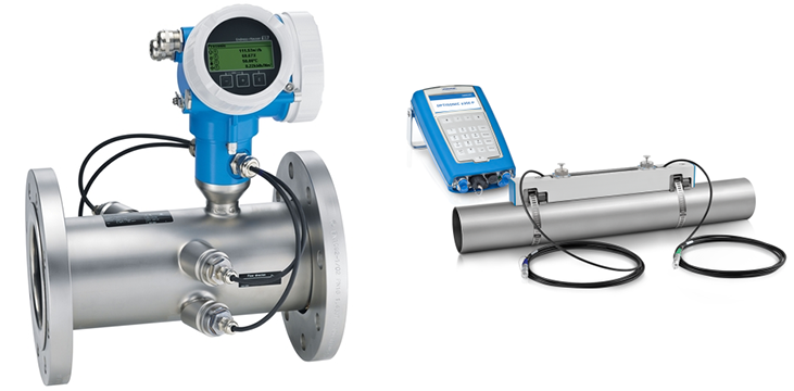
Ultrasonic Flowmeter
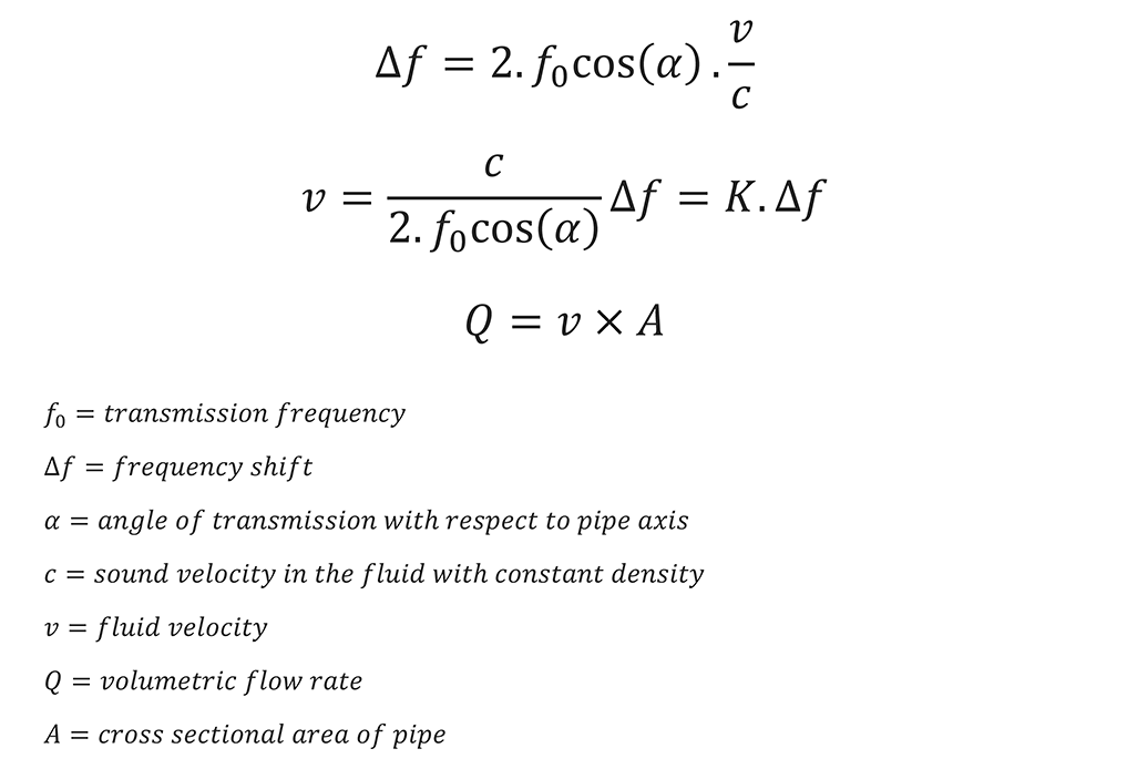
Ultrasonic flowmeter is a volumetric flowmeter for liquid, gas and steam services.
Ultrasound is sound wave with frequency higher than human hearing range which is 20HZ to 20KHZ.
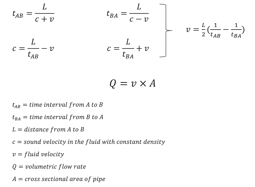
Sound wave velocity in a medium depends on its density.
In a medium with a constant density the sound velocity is constant.
When the medium is in motion the total travel velocity is summation of sound wave velocity and the medium velocity.
Therefore by measuring an ultrasonic wave travel time from point A to point B in a medium we can measure the medium velocity which guide to medium flow measurement.
Ultrasonic Flowmeter Types
There are two types of ultrasonic flowmeter:
- Transit-Time (Time-of-Flight)
- Doppler
Transit-Time (Time-of-Flight) Flowmeter
If we transmit a sound impulse in the same direction of the flow from point A to point B in a fluid with a constant density, it travels the distance between two points after a time interval, which will be measured.
Its velocity is summation of sound velocity and fluid velocity.
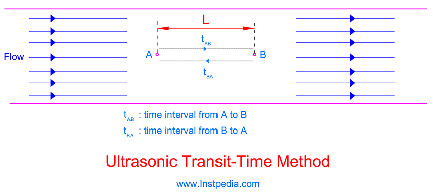
Then if we transmit the sound impulse back from point B to point A the time interval will be different and sound impulse velocity is subtraction of fluid velocity from sound velocity.
In another word sound impulse will be accelerated in the direction of flow and decelerated against the flow.
By measuring the time intervals, fluid velocity and then volumetric flow rate can be calculated according to the following equations:
In real transit-time ultrasonic flowmeters, sound impulse transmission path has an angle with respect to pipe axis.
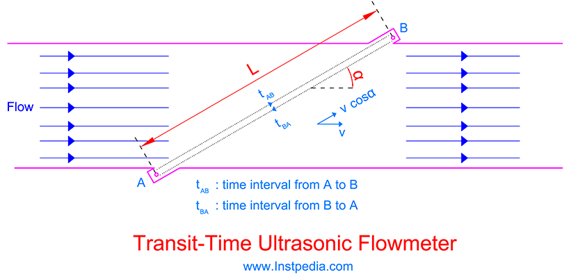
Sound impulse velocity and medium velocity are not in the same direction, hence the above equations will be as the following:
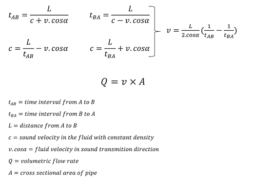
Please note that if medium's density varies due to changes in other physical parameters such as pressure or temperature, therefore the sound velocity cannot be constant during measurement and affects the accuracy, hence proper compensation should be considered.
Transit-time flowmeters are used for mediums that are clean and have acoustic transparency, which means that solid particles or bubbles in the medium should be very few.
Doppler Flowmeter
Doppler ultrasonic flowmeter works based on Doppler Effect.
In 1842 an Austrian physicist, Christian Doppler, described the change of frequency of a wave, while wave source is moving in relative to the observer.
When the distance is decreasing, the frequency of the received wave will be higher than the source wave.
And the frequency of the received wave will be lower than the source wave, when the distance is increasing.
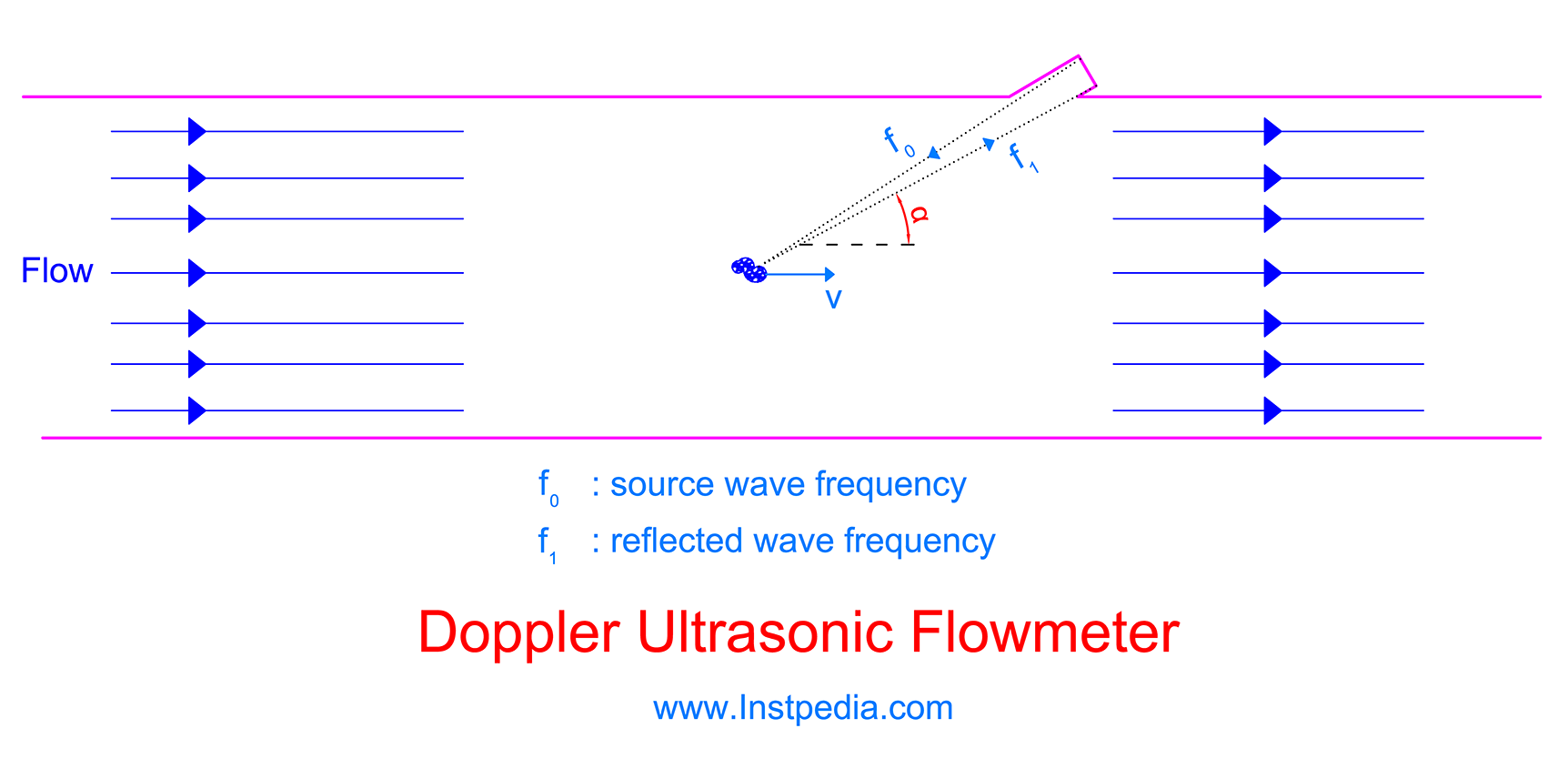
Doppler ultrasonic flowmeter uses solid particles or gas bubbles in the medium that have the same velocity as medium velocity, to reflect the transmitted ultrasonic wave.
Then measures the frequency shift of the reflected wave which is a function of medium velocity according to the Doppler Effect.
Apparently impurities, solid particles or gas bubbles are essential for flow measurement by Doppler ultrasonic flowmeter in contrast with Transit-Time ultrasonic flowmeter.
For proper flow measurement by Doppler flowmeter, the liquid needs to contain at least 100ppm of suspended solids or bubbles with minimum size of 100 microns.
Multi-Path Design
Ultrasonic flowmeter measurement is affected by medium's velocity profile.
Ultrasonic flowmeter with one beam (Single Path) can be accurate enough if flow profile is symmetrical and swirls and piping equipment affects are controlled by preparing sufficient straight pipe run.
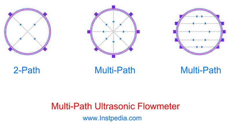
In order to attenuate velocity profile variation effect on ultrasonic flowmeter accuracy, two or more beams (Multi-Path) will be used around the pipe.
Therefore in applications, where accuracy is critical such as custody transfer metering systems, only Multi-Path ultrasonic flowmeters are acceptable.
Ultrasonic flowmeter Installation
Ultrasonic flowmeter is available in two installation designs:
- Inline
- Clamp-on
In inline flowmeter, ultrasonic transducers are installed precisely on a pipe spool by manufacturer with flange connection which will be installed directly in pipe line.
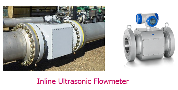
In this design transducers are in contact with the medium and transmit the ultrasonic impulse inside the pipe.
In clamp-on design, ultrasonic transducers are installed outside the pipe and the transducers are not in contact with the medium (non-contact design).
In this design, ultrasonic waves should traverse the pipe wall twice to reach the receiver which reduces meter sensitivity and increases the acoustic impedance.
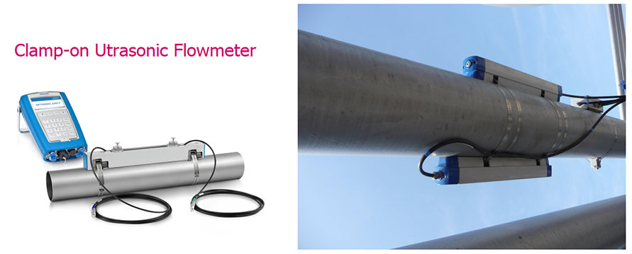
Since clamp-on ultrasonic flowmeter is a non-contact flowmeter, it could be a good solution for corrosive, erosive or toxic services.
Also for very large pipe sizes, clamp-on ultrasonic flowmeter is an accurate and economical option.
Clamp-on ultrasonic flowmeter has the advantage of being installed or removed without process line shutdown.
Clamp-on ultrasonic flowmeter installation is not complicated, but reflection and refraction must be considered during installation or calibration.
Since inline ultrasonic flowmeters do not have pipe wall transmission losses and noises of reflections between pipe boundaries, they have more acoustic power and have better signal-to noise ratio than clamp-on ultrasonic flowmeters.
Ultrasonic flowmeters can be installed in vertical and horizontal pipe lines.
Ultrasonic Flowmeter Straight Run Requirement
Single path ultrasonic flowmeter straight pipe run requirements are similar to those for orifice plates.
For multi-path ultrasonic flowmeter required straight run is about 10D for upstream and 3D for downstream.
Using flow conditioner before inline ultrasonic flowmeter could reduce the length of required upstream straight run magnificently.
Ultrasonic Flowmeter Accuracy
Ultrasonic flowmeter accuracy depends on size and velocity range.
As smaller the size and velocity the higher the accuracy.
Typically inline ultrasonic flowmeter accuracy is 0.1% up to 0.5% of measured flow rate by multi-path flowmeter for custody transfer applications and 0.3% up to 1% of measured flow rate by single path flowmeter for ordinary applications.
Clamp-on ultrasonic flowmeter accuracy is 1% up to 3% of measured flow rate, if it is installed and calibrated precisely with consideration of reflections or refractions.
Ultrasonic Flowmeter Rangeability
Rangeability or turndown ratio is the ratio of maximum to minimum measurable flow rate with the defined accuracy.
Transit-time ultrasonic flowmeter rangeability could be 30:1 up to 100:1.
Doppler ultrasonic flowmeter rangeability could be 20:1 up to 100:1.
Ultrasonic Flowmeter Advantages
- High accuracy
- Large rangeability up to 100:1
- Multi-path design is available for custody transfer applications
- Good for low flow measurements
- Suitable for corrosive, erosive or toxic services
- Proper for cryogenic services
- Available for very large pipe lines
- Bi-directional flow measurement
- Suitable for high temperature and pressure services
- No moving part
- No pressure drop
- Clamp-on design is suitable for non-contact temporary measurement
Ultrasonic Flowmeter Limitations
- High price
- Reflection and refraction must be considered for Clamp-on design
- Solid particles or bubbles affect transit-time type performance
- Straight pipe run of 10D for upstream and 3D for downstream for multi-path and more for single line is required
- Not suitable for two phase services
Turbine Flowmeter
Reinhard Woltman, a German engineer innovated the first turbine flowmeter in 1970.
Turbine flowmeter generally, consists of a revolving turbine and at least one pickup coil.
Turbine is a vaned rotor that can revolve freely on a bearing in the fluid about an axis along the center line of the pipe.
Flow impinges upon the turbine blades and causes the turbine to revolve.
A pickup coil monitors the turbine rotation by counting the turbine's blades passes.
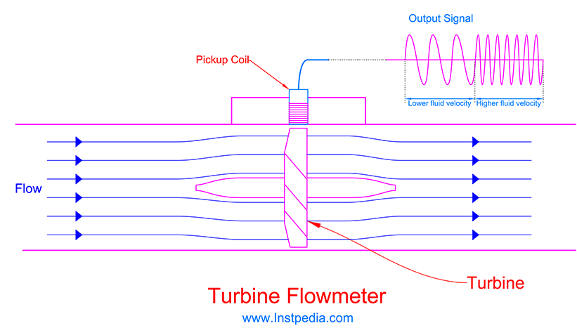
Turbine rotation angular velocity is proportional to the fluid velocity.
Pickup coil provides pulses as an output with a frequency proportional to the turbine angular velocity as a result of fluid velocity.
Turbine flowmeter calculates the fluid velocity from pickup coil output frequency and finally the volumetric flow rate.
Sensing Methods of Pickup Coil
There are three methods that could be used in pick up coils for turbine rotation monitoring:
- Method 1
- A permanent magnet in one of the turbine vanes induces a voltage in pickup coil in each turbine rotation.
- Frequency of induced voltage pulses determines the fluid velocity.
- Method 2
- Pickup coil produces a magnetic field which is distorted by turbine vanes made of ferromagnetic material.
- Magnetic field distortion produces voltage pulses with a frequency proportional to angular velocity of the turbine.
- Method 3
- An AC voltage is applied to the pickup coil which its amplitude will be changed by turbine ferromagnetic vanes passes.
- The output is a superimposed frequency on AC voltage supply frequency (carrier frequency).
- This secondary superimposed frequency is proportional to turbine angular velocity.
Special Design Turbine Flowmeters
The general and most common turbine flowmeter in different industries described formerly, but for some applications innovative designs are available that provide higher reliability and accuracy or reducing the cost which are described in the following.
Twin-Turbine Flowmeter
Twin-Turbine flowmeter first designed for aerospace to provide more reliability, higher accuracy and rangeability, also to decrease bearing wear.
In this design there are two turbines, one in the upstream the other one in downstream of the flowmeter.
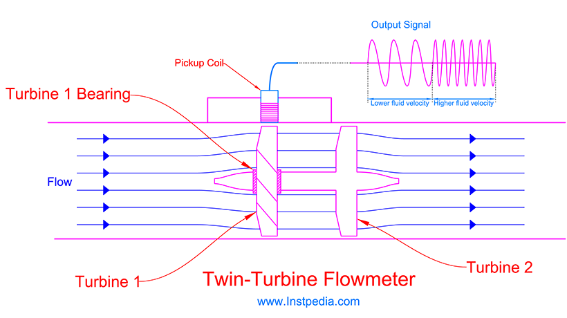
The downstream turbine is fixed to the revolving shaft and rotates the shaft as the flow impinges upon its blades.
The upstream turbine has the main responsibility of flow measurement and it is not fixed on the shaft and can rotates on the shaft using a bearing while the shaft is rotating itself at the same direction a very small relative velocity to upstream turbine.
This design decreases the upstream turbine bearing wear and friction and helps the rotor to revolve with smaller torque from smaller fluid's velocities and flowrates, which improves rangeability for liquid services up to 200:1 and for gas services up to 1000:1.
Twin-Turbine flowmeters are widely used in aerospace, military and precise physiological measurement applications because of high accuracy, reliability and rangeability.
Dual-Turbine Flowmeter
Dual-Turbine flowmeter has two turbines like Twin-Turbine flowmeters but angle of vanes in upstream turbine differs from the one in downstream turbine, also each turbine has its own independent shaft.
Upstream turbine vane angle is higher than downstream turbine vane angle, therefore upstream turbine rotates with a slower angular velocity.
Flow rate is calculated from angular velocity difference of the two turbines.
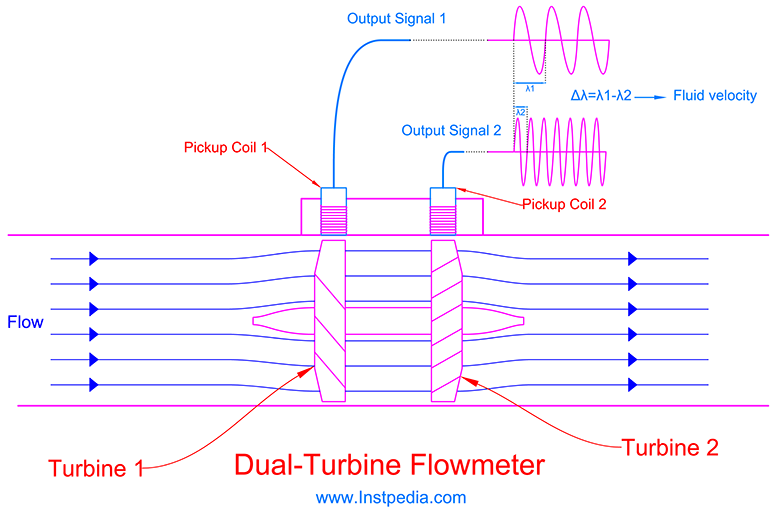
Mostly the downstream turbine angles are designed in a form that rotates in opposite direction of upstream turbine and very faster.
Dual-Turbine flowmeter design improves the rangeability up to 500:1 in gas services, because downstream turbine rotates faster in low flow rates.
Since downstream turbine rotates very fast, its bearing is subject to wear and requires periodic maintenance or automatic lubrication facilities.
Dual-Turbine flowmeters are less reliable than Twin-Turbine flowmeter due to higher bearing wear risk.
Dual-Turbine flowmeters are mostly used in clean gas services and particularly in natural gas pipe lines for flow measurement.
Paddle Turbine Flowmeter
Paddle Turbine flowmeter is not as accurate as other turbine flowmeters, but its low cost is considerable.
Paddle Turbine flowmeter is usually used for flow measurement in large pipe sizes and where accuracy is not critical.
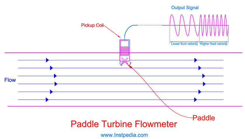
In order to have an acceptable accuracy, Paddle Turbine flow meter should be used for turbulent flow with Reynolds Number above 4000 that velocity at center of the pipe is almost the same as the velocity near the pipe wall.
Turbine Flowmeter Material
AISI 316 / 316L / 316Ti Stainless Steels could be the best and the most common material for body, blade, bearing and shaft material and any other wetted part due to proper resistance against corrosive services and acceptable mechanical properties with temperature range of -254 to 816°C.
For services that contain an aggressive species such as chloride (Cl-), like seawater, 316SS or 316L SS could not be used, but Hastelloy C, which is a Nickle Alloy with PREN (Pitting Resistance Equivalent Number) greater than 40 is recommended for such services.
Where more mechanical strength with acceptable corrosion resistance is needed, Precipitation Hardening Stainless Steels such as 17-4PH (ASTM A564 Grade 630) could be a good selection for blade and shaft material.
In very high velocity services, Tungsten Carbide which is a ceramic material with high temperature and erosion resistance properties, could be proper for bearing material.
Turbine Flowmeter Accuracy
Basic Single Turbine flowmeter accuracy is 0.25% up to 1% of reading value.
Twin-Turbine flowmeter is the most accurate model with accuracy of 0.1% up to 0.5% of reading value.
Dual-Turbine flowmeter accuracy is 0.25% up to 0.5% of full scale and suitable for natural gas custody transfer metering systems.
Paddle Turbine flowmeter accuracy is 2% up to 5% of reading value, which is the lowest accuracy in comparison with other turbine flowmeter types.
Turbine Flowmeter Rangeability
Rangeability or turndown ratio is the ratio of maximum to minimum measurable flow rate with the defined accuracy.
Single Turbine flowmeters rangeability is about 10:1 up to 30:1.
Twin-Turbine and Dual-Turbine flowmeters improved the rangeability of turbine flowmeter.
Dual-Turbine flowmeter are mostly used in gas services with rangeability up to 500:1.
Twin-Turbine rangeability for liquid services is 200:1 and for gas services up to 1000:1.
Turbine Flowmeter Straight Run Requirement
Required straight run for turbine flowmeter is about 20D for upstream and 5D for downstream.
Using flow conditioner before inline turbine flowmeter could reduce the upstream straight run to 10D.
Turbine Flowmeter UVC Calibration
Kinematic viscosity effects the turbine flowmeter, therefore it should be calibrated at operating kinematic viscosities.
The Universal Viscosity Curve (UVC) is a method of presenting meter data over a kinematic viscosity range.
In Universal Viscosity Curve calibration, the meter output frequency will be measured typically in 10 points for each kinematic viscosities in a range.
The result is a K factor for the turbine meter.
If we plot the graphs of K versus f/v (output frequency ÷ kinematic viscosity) for all the calibration points of different kinematic viscosity, we determine a region that curves cover each other, meaning that K factor remains approximately constant in that region and form a horizontal straight line.
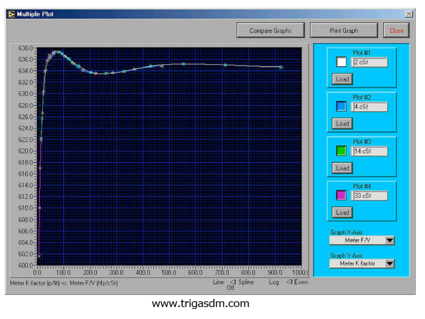
This K factor will be used for viscosity compensation for volumetric flowrate calculation.
There is another methods that compensates the calculations for meter thermal expansion which is called Strouhal versus Roshko method.
Turbine Flowmeter Applications
Turbine flowmeters are suitable for custody metering of liquids and gases due to high accuracy.
Single Turbine flowmeters are mostly used for natural gas custody metering, gasoline or diesel metering in gas stations and residential water metering.
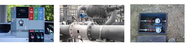
Twin-Turbine flowmeters are widely used in aerospace, military and precise physiological measurement applications because of high accuracy, reliability and rangeability.
Dual-Turbine flowmeters are mostly used in natural gas custody metering systems.
Paddle Turbine flowmeters are used for very large pipelines flow measurement due to low cost and in applications where accuracy is not critical.
Turbine Flowmeter Advantages
- High accuracy
- Suitable for custody metering
- Low pressure drop
- High rangeability
- Bi-directional measurement
Turbine Flowmeter Limitations
- Moving parts are subject to wear
- High Cost
- Not suitable for slurries
- Recalibration is required after years of operation
- Flow conditioner is needed
Vortex Flowmeter
Vortex Flowmeter (Vortex Shedding Flowmeter) is another type of volumetric flowmeters that measures velocity of the flowing medium.
Vortex flowmeter works based on Karman Vortex Street phenomenon, which is named after Theodore von Kármán, a Hungarian-American mathematician, physicist and aerospace engineer.
Based on Karman Vortex Street, as the flow passes an object, it creates a vortex on one side of the object on the downstream.
Then a similar vortex will be formed on the other side of the object.
Alternate vortices on both side of the object results a shedding vertexes series which are called Karman Vortex Street.
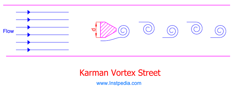
Vincenc Strouhal, a Czech physicist, discovered that frequency of shedding vortexes are function of bluff body (object) geometry and the medium velocity.
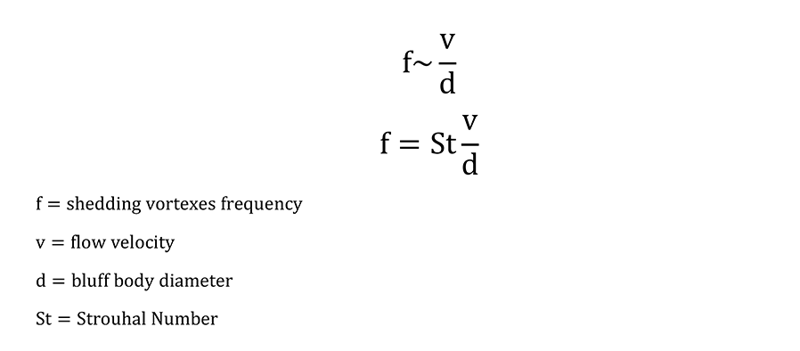
The proportionality constant of this equation is named Strouhal Number.
Vortex Flowmeter measures the shedding vortexes frequency and calculates fluid velocity based on the above equation and finally derives volumetric flow rate.
When each of vortexes shed after the bluff body it changes the pressure distribution.
Hence alternate vortex shedding can create frequent lateral forces.
There are various methods to determine vortexes frequency such as using diaphragm pressure sensor, capacitance sensor or Piezo-electric crystal sensor.
One of the ways for vortexes frequency measuring is to locate a bouncing paddle after the bluff body that could move and vibrate with the mentioned lateral forces.
Since the paddle moves to low pressure side after each vortex shed, its bouncing frequency is equal to vortex shedding frequency.
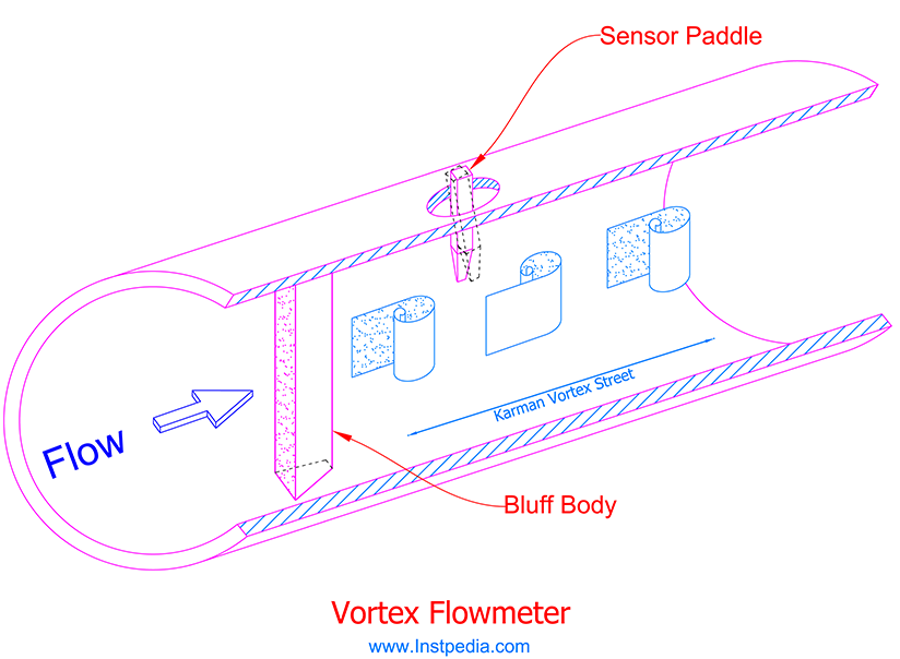
As an option, vortex flowmeter could be equipped with integrated temperature sensor, pressure transmitter and a flow computer for PT compensation for density or mass flow calculations.
Flow computer on vortex flowmeter can accept signal from external temperature and pressure transmitters for mentioned calculations.
For steam services integrated temperature sensor could be helpful for steam dryness calculation, condensate hammering probability warning or heat calculation.
Some manufacturers have provided signal processing or filtering for better accuracy and to provide vibration immunity especially in low flow conditions.
Vortex Flowmeter Selection & Sizing
For very viscous fluids with laminar flow profile, vortexes will not appear after the bluff body, so Vortex flowmeter is not suitable for such services.
In order to achieve best and accurate flow measurement by Vortex flowmeters, Reynolds Number of fluid should not be less than 20000.
In low flow conditions where velocity is extremely low, Vortex flowmeter size could be selected less than pipe size in order to assure optimum accuracy and rangeability.
Care should be taken to avoid cavitation in liquids services and sonic velocity flow in gases services, while reducing the Vortex flowmeter size.
Manufactures' sizing software provides the best size selection for Vortex flowmeters considering viscosity, Reynolds Number, velocity range, optimum accuracy, cavitation and sonic velocity.
Vortex Flowmeter Material
AISI 316 / 316L / 316Ti Stainless Steels is the most common material for body, bluff body and sensor and any other wetted part due to proper resistance against corrosive services and acceptable mechanical properties with temperature range of -254 to 816°C.
For services that contain an aggressive species such as chloride (Cl-), like seawater, 316SS or 316L SS could not be used, but Duplex & Superduplex alloys or Nickle Alloy such as Hastelloy C with PREN (Pitting Resistance Equivalent Number) greater than 40 are recommended.
Vortex Flowmeter Applications
Vortex flowmeter is widely used for liquid, gas and steam flow measurement, where rangeability and accuracy are required.
Vortex flowmeter is not suitable for services with solid particles, two phase services or for pulsating flow conditions.
Vortex flowmeter could not perform in very viscous services like slurries, because Karman Vortex Street will not take place in such services.
Meaning that Vortex flowmeter will not perform accurately if the fluid's Reynolds Number is less than 20000, unless for pipe sizes less than 4" but conditional to manufacturer calculation and confirmation.
Vortex flowmeter is a good selection for saturated steam or superheated steam for flow measurement and steam heat calculation using an integrated temperature transmitter.
Where mass flowmeters are not affordable, Vortex flowmeters is an economic selection for mass flow or density measurement with an acceptable accuracy in collaboration with PT compensation.
Also Vortex flowmeters could be used for cryogenic services flow measurement.
Vortex Flowmeter Accuracy
For liquids: 0.5% up to 0.75% of full scale
For gases and steam: 1% up to 1.5% of full scale
Please note that the mentioned accuracies are for services with Reynolds Number greater than 20000.
For less Reynolds Number accuracy decreases to 2% of full scale for liquids and 2.5% of full scale for gasses and steam.
Vortex Flowmeter Rangeability
Rangeability or turndown ratio is the ratio of maximum to minimum measurable flow rate with the defined accuracy.
Vortex flowmeters rangeability is generally about 10:1, but for Reynolds Numbers more than 20000 it could reach 20:1.
Vortex Flowmeter Straight Run Requirement
Required straight run for turbine flowmeter is at least 15D for upstream and 5D for downstream.
If there is a valve or double elbow at upstream of the meter, the required upstream straight run increases to 20D.
Vortex Flowmeter Advantages
- Good accuracy
- High rangeability for turbulent flow
- Available for large size pipes
- Linear measurement
- Low cost
- Long term stability of calibration
- Low maintenance and high reliability
- Digital signal processing and filtering is available for vibration compensation
- Suitable for high temperature services
- Suitable for cryogenic services
- Economic selection for mass flow / density measurement with PT compensation with acceptable accuracy
- Suitable for saturated / superheated steam energy calculation with integrated temperature sensor
Vortex Flowmeter Limitations
- Not accurate for services with Reynolds Number less than 20000
- Not applicable for slurries
- Not suitable for services with erosive solid particles
- Not suitable for pulsating flows
- High pressure drop (because of bluff body)
- One direction flow measurement
Swirl Flowmeter
Swirl (Vortex Precession) Flowmeter is another type of volumetric flowmeters.
Swirl flowmeter is very similar to Vortex Shedding flowmeter but instead of bluff body there is a stationary turbine that rotates as the medium flows through it and force the medium to rotate, too and creates swirl flow at downstream.
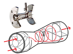
The frequency of the created swirl is linearly proportional to the medium velocity and finally the flow rate.
The higher the flow rate indicating the higher swirl frequency.
This frequency is detected by the same sensor in vortex shedding flowmeter which is usually a Piezo-electric crystal sensor.
After the sensor a flow straightener inside the meter, damps the swirls and modifies the flow profile to avoid affecting other equipment.
Swirl flowmeters can be used for measuring the flow of liquids, gases and steam.
Swirl Flowmeter Straight Run Requirement
Required straight run for swirl flowmeter is at least 3D for upstream and 1D for downstream which is magnificently less than vortex shedding flowmeter.
If there is a valve or double elbow at upstream of the meter, the required upstream straight run increases to 5D.
Swirl Flowmeter Accuracy
Accuracy for Swirl Flowmeter is 0.5% of full scale for liquids, gasses and steam.
Swirl Flowmeter Rangeability
Rangeability or turndown ratio is the ratio of maximum to minimum measurable flow rate with the defined accuracy.
Swirl flowmeters rangeability is about 50:1, which is an impressive improvement in comparison to Vortex flowmeter.
Swirl Flowmeter Advantages
Swirl flowmeter has all the Vortex flowmeter advantages, but has the following advantages in addition:
- Higher accuracy (0.5% of full scale for liquids, gases and steam)
- Higher rangeability (50:1)
- Magnificently less upstream and downstream straight run
Positive Displacement Flowmeter
Positive Displacement flowmeters are another type of volumetric flowmeters with moving parts that transfer a specific, geometrically limited volume of medium with each cycle of movement.
Positive Displacement flowmeters operates based on the principle of trapping and then releasing a defined fluid pockets.
Since each pocket contains a specific fluid volume, counting cycles of trapping and releasing of pockets in a time interval provides the volumetric flow rate of the fluid.
Positive Displacement flowmeters are suitable for flow measurement of liquids and gases.
Positive Displacement flowmeters are the most accurate flowmeter for clean and viscous fluids.
The higher the viscosity the higher the accuracy.
High viscosity increases the accuracy, but decreases the slippage of the medium and measuring flow range, also increases the pressure drop.
Positive Displacement Flowmeter Types
There are different types of Positive Displacement (PD) flowmeters, but the most applicable types in industries are as the following:
- Nutating Disc
- Oval Gear
- Lobed Impeller
- Oscillating Piston
Nutating Disc PD Flowmeter
Nutating Disc flowmeter consist of a disc in center of a sphere ball locating inside a chamber.
Flow pushes the disc down and wobbles the ball, then the trapped fluids will be released by exceeding the flow force and rotation of the ball.
By each rotation and wobbling of the disc and ball, specific volume of the fluid is passed to the outlet.
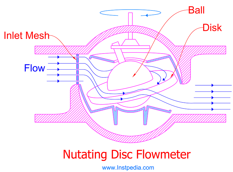
Nutating Disc flowmeter are mostly used as residential water flowmeter.
Oval Gear PD Flowmeter
Oval Gear Positive Displacement flowmeter consists of two toothed oval gears that rotate in contact with each other.
Oval Gear flowmeter is used for liquids flow measurement.
The fluid flow produces the required torque to rotate the gears and force them to rotate in opposite directions.
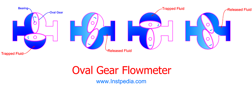
Each rotation of the pair of oval gears traps and then releases a defined fluid volume.
The number of rotations is an exact measure of the quantity of fluid which has flowed through the meter.
The gears and bearings of Oval gear flowmeter are subject to mechanical wear, therefore using this flowmeter for liquids with lubricating properties minimize the wearing.
Oval Gear flowmeters are used for high accuracy flow measurement of very viscose liquids, where other flowmeters have problems.
Its accuracy increases with rise in viscosity.
Lobed Impeller PD Flowmeter
Lobed Impeller Positive Displacement flowmeter is very similar to Oval Gear flowmeter but for gases.
It consists of two rotating impellers, designed with cross section in shape of the eight number.
The gas being measured forces the impellers to rotate in opposite directions.
For synchronizing the impellers rotation, a gear is considered outside of the measuring chamber.
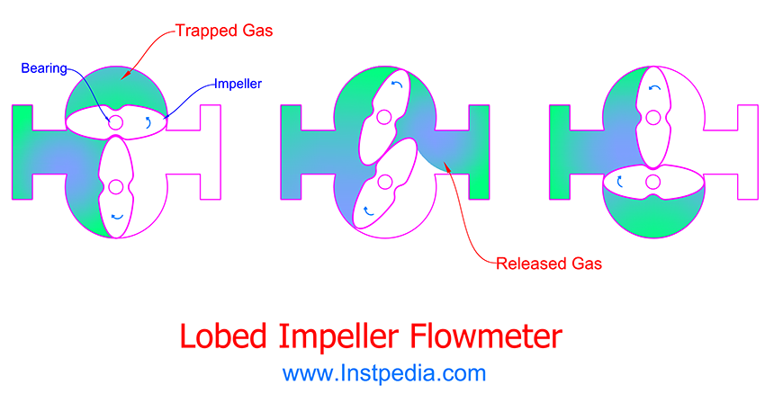
There are some leakages from the gaps between the impellers which is unmeasured flow, but it could be compensated.
Viscosity of gases increases in high temperature which reduces the amount of leakage and unmeasured flow.
The cycles of trapping and releasing the gas, causes pulsation flow and vibration or noise in piping system.
Oscillating Piston PD Flowmeter
Oscillating Piston Positive Displacement flowmeter consists of stationary cylindrical chamber with two openings (ports) and one oscillating piston which oscillates eccentrically inside the chamber by flow force.
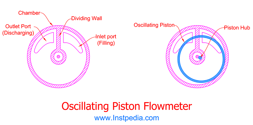
The chamber or housing has a dividing wall between the ports.
One of the ports is inlet port for filling the chamber and the other port is outlet port for discharging the chamber.
The dividing wall and oscillation of the piston provides two sections with capacity of two different volumes of fluid.
The first volume section (Volume 1) is between dividing wall and inside of the piston.
The Second volume section (Volume 2) is between dividing wall and outside of the piston.
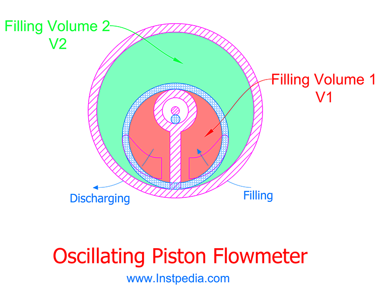
During each oscillation of piston, volume 1 and volume 2 are filled by inlet port and then discharged by outlet port respectively.
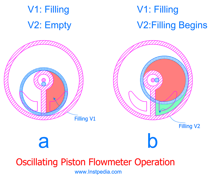
In figure (a), piston is in a position that inlet port fills the section between dividing wall and the inside of the piston which is half of the volume 1 section.
Then in figure (b), most of the volume 1 section is filled and as the piston passes the inlet port, the section between dividing wall and the outside of piston starts being filled which is a portion of volume 2.
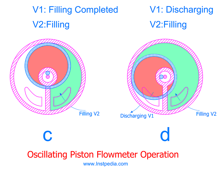
In figure (c), volume 1 section is completely filled with fluid and half of volume 2 section is filled, too.
In position (d), as the oscillation piston moves on outlet port and volume 1 section starts discharging while volume 2 section is still being filled.
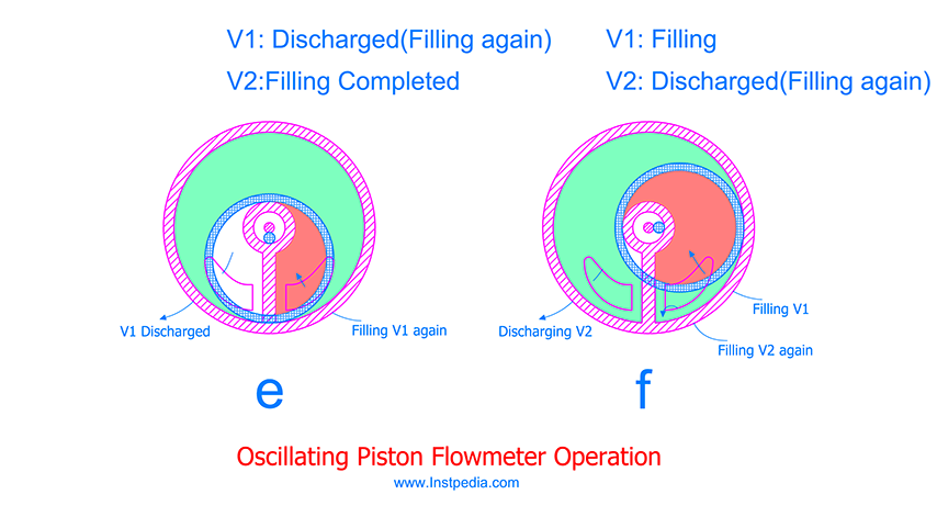
In figure (e), volume 2 section is completely filled and the first fill of volume 1 section is completely discharged.
But again half of the piston is on inlet port, therefore half of the volume 1 section starts being filled for the second time.
In figure (f), volume 2 section starts discharging, while on the other side of dividing wall a portion of volume 2 section starts being filled for the second round.
In the next move the same as figure (c), second round of volume 1 section is completely filled and half of the volume 2 section is filled again, too.
With each oscillation of the piston, volume 1 and volume 2 sections are filled and discharged once.
In another word in each oscillation, flowmeter has passed the volume of fluid equal to summation of volume 1 and volume 2.
Hence counting the piston oscillation cycles in a specific time interval guides to volumetric flow rate.
Oscillating Piston Flowmeter are especially used for water and oil services flow measurement.
This flowmeter's parts are subject to wear, therefore special care should be taken for material selection also they should be used in services of fluids with lubricating characteristics.
The same as other PD flowmeters, Oscillating Piston Flowmeter accuracy increases with increase in viscosity.
Positive Displacement Flowmeter Applications
Positive Displacement flowmeters are suitable for flow measurement of liquids and gases.
In high viscosity gas or liquid services, slipping of medium decreases, therefore PD flowmeters accuracy increases.
Hence, Positive Displacement flowmeters are the most accurate flowmeters for clean and viscous services.
Nutating Disc, Oval Gear and Oscillating Piston flowmeters are used for liquids flow measurement, while Lobed Impeller flowmeter is proper for gas flow measurement.
Positive Displacement flowmeters are subject to wear, therefore they should be used for services with lubricating characteristics.
They are especially used for water and oil services custody flow measurement.
Nowadays they are seldom used in petrochemical and refinery industries.
However they are still in use in residential water metering, gas stations, oil industry custody metering.
Positive Displacement Flowmeter Accuracy
Positive Displacement flowmeters accuracy is 0.1% up to 0.5% of full scale for liquids and 1% of full scale for gases.
The higher the viscosity the higher the accuracy.
Positive Displacement Flowmeter Rangeability
Rangeability or turndown ratio is the ratio of maximum to minimum measurable flow rate with the defined accuracy.
Positive Displacement flowmeters rangeability is 30:1 up to 100:1.
Positive Displacement Flowmeter Advantages
- Suitable for viscous services
- High accuracy
- High rangeability
- Do not require upstream straight run
- Do not require external power
Positive Displacement Flowmeter Limitations
- Moving parts are subject to wear
- Produce pulsation and vibration at downstream
- High maintenance effort
- Not long lasting accuracy due to wear
- Low accuracy for low viscosity fluids
Target Flowmeter
Target flowmeter is another type of volumetric flowmeters.
It measures forces caused by flow impact on a disk suspended in the middle of pipe line, which is proportional to velocity head.
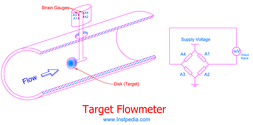
Flow impact force is converted by strain gauge bridge circuitry, into a voltage signal which is proportional to the square of the flow rate.
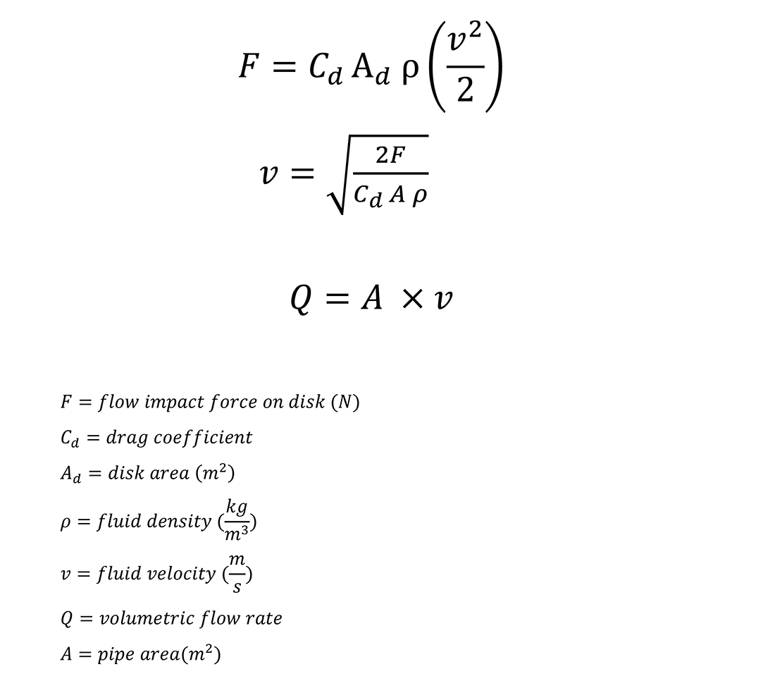
Target flowmeter is used for flow measurement for liquids, vapors and gasses.
Target flow meter is mostly used for slurries and gasses with condensate or other difficult services where orifice plates has major problems for flow measurement.
Target flow meter is widely used as flow switch for pumps low flow protection.
Target Flowmeter Accuracy
Target flowmeter accuracy is 1% up to 3% of full scale.
Target Flowmeter Rangeability
Rangeability or turndown ratio is the ratio of maximum to minimum measurable flow rate with the defined accuracy.
Target flowmeter rangeability is 10:1.
Target Flowmeter Advantages
- Low cost
- Low pressure drop (probe design)
- Probe design is suitable for large pipes
- Bi-directional flow measurement is possible
- Suitable for pumps low flow protection
Target Flowmeter Limitations
- Not suitable for erosive or corrosive services
- Low accuracy
The following website could be very helpfull for additional information about flowmeters and suppliers: