Temperature Instruments
Various Units of Temperature Measurement
- °C – degrees Celsius (or Centigrade)
- °F – degrees Fahrenheit
- K – Kelvin
- R – Rankine
Relationship between different units
- °C = (°F - 32)/1.8
- °F = 1.8 x °C + 32
- K = °C + 273.15
- R = °F + 459.67
Types of Temperature Instruments
The most common temperature instruments are used in industrial plants are as the following:
- Thermocouple (T/C)
- Resistance Temperature Detector (RTD)
- Thermistor
- Bi-metallic Thermometers
- Filled Thermal Systems
- Infrared
Thermocouple (T/C)
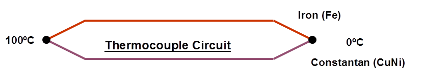
Thermocouple measuring circuit
In 1821 Seebeck, a German physicist, discovered the thermoelectric effect which forms the basis of modern thermocouple technology.
He observed that an electric current flows in a closed circuit of two dissimilar metals if their two junctions are at different temperatures. It means that a thermoelectric voltage is produced between the two points.
The thermoelectric voltage produced depends on the metals used and on the temperature relationship between the junctions.
If the same temperature exists at the two junctions, the voltage produced at each junction cancel each other out and no current flows in the circuit.
With different temperatures at each junction, different voltages are produced and current flows in the circuit.
A thermocouple can therefore only measure temperature differences between the two junctions, a fact which dictates how a practical thermocouple can be utilized.
Thermocouples measure the temperature difference between two points, not absolute temperature. To measure a single temperature, one of the junctions(the cold junction)is maintained at a known reference temperature, and the other junction is placed at the point that its temperature is going to be sensed.
Target point temperature is derived from the following formula:
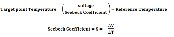
Seebeck coefficient is different for each material at room temperature.
Having a junction of known temperature, while useful for laboratory calibration, is not convenient for most measurement and control applications.
Instead, they incorporate an artificial cold junction using a thermally sensitive device such as a thermistor or diode to measure the temperature of the input connections at the instrument, with special care being taken to minimize any temperature gradient between terminals.
Hence, the voltage from a known cold junction can be simulated, and the appropriate correction applied. This is known as cold junction compensation.
Some integrated circuits are designed for cold junction temperature compensation for specific thermocouple types.
Thermocouple construction
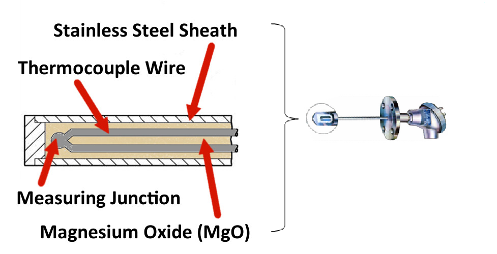
- Normally element is in a thermowell.
- Commonly element's outside Diameter is 1/4”.
- Sheath material, is normally Stainless steel but can be special material such as Inconel, Incoloy, Hastelloy, Monel etc.
- Duplex thermocouples have 2 elements inside one sheath.
Standard Thermocouple Alloy Conductor Combinations
| CODE | CONDUCTOR COMBINATION | TYPICAL OPERATING RANGE ºF |
|---|---|---|
| B | Platinum-30% Rhodium / Platinum-6% Rhodium | +2500 to +3100 |
| C | Tungsten-5% Rhenium / Tungsten-26% Rhenium | +3000 to +4200 |
| D | Tungsten-3% Rhenium / Tungsten-25% Rhenium | +2800 to +3800 |
| E | Nickel Chromium / Constantan | 0 to +1650 |
| J | Iron / Constantan | +0 to +1400 |
| K | Nickel Chromium / Nickel Aluminium | 0 to +2300 |
| N | Nickel-Chromium-Silicon / Nickel-Silicon-Magnesium | 1200 to +2300 |
| R | Platinum-13% Rhodium / Platinum | 1600 to +2600 |
| S | Platinum-10% Rhodium / Platinum | 1800 to +2600 |
| T | Copper / Constantan | -300 to +650 |
Different color is defined for extension wires in standards for different thermocouple types.
In API 551 the thermocouple types and recommended ranges of ISA/ASTM standard are specified as the following table:
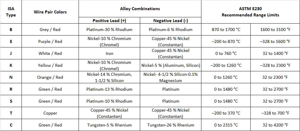
Note: for very high temperature applications, Ceramic thermowell shall be used.
Thermocouples must be selected to meet application conditions considering:
- Temperature (select type J, K, M, T or other)
- Response time (larger diameter reduce response time)
- Service life (larger diameter increases service life)
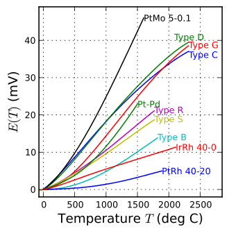
As mentioned before Seebeck coefficient is different for each material at room temperature, therefore each thermocouple type has a different Seebeck coefficient:
| Thermocouple Type | Seebeck coefficient at room temperature(µV/ºC) |
|---|---|
| J | 50 |
| K | 40 |
| E | 60 |
| R | 11 |
| S | 10 |
| T | 38 |
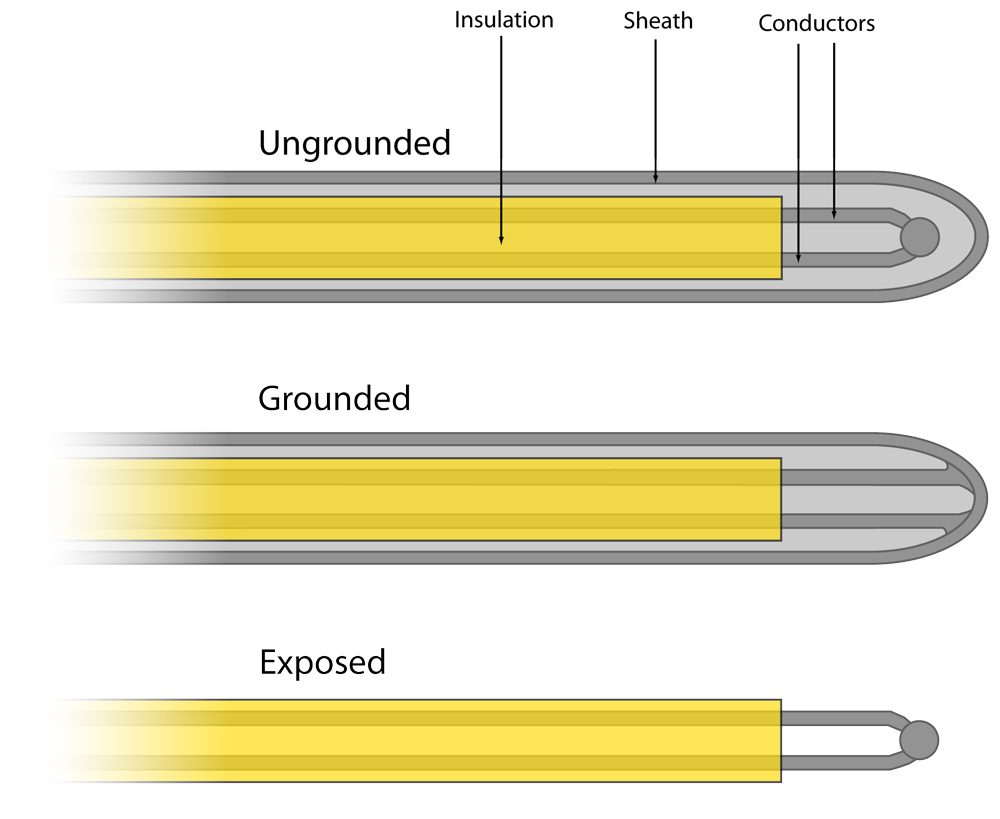
Junction Types
There are two types of measuring junction is generally used:
- Type A (Grounded) has a grounded tip welded to the sheath for fast response and lower electrical noise.
- Type B (Ungrounded) has an ungrounded tip and is electrically isolated from the sheath. It has a slower response.
Exposed (bare wire thermocouple) in which the junction is outside the sheath and in direct contact with the process fluid is not recommended.
Following standards define thermocouples
- IEC 60584-1: Thermocouples: basic and tolerance values of the thermoelectric voltages
- IEC 60584-3: Thermocouples: Thermocouple cables and compensating cables
- ASTM E230: Standard specification and temperature-electromotive force (EMF) tables for standardized thermocouples.
Thermocouple Accuracy
The generated voltage of the Thermocouples are weak, in millivolt range, and the absolute error of transmitters is considered as 0.01mv, so the error would be less than 1ºC.
For small temperature spans this error is not acceptable, therefore it is recommended to use Thermocouples in high temperatures.
For measurements in the lower to middle temperature range (-200 ... +600 °C), commonly Pt100 RTDs are used.
The total error is the sum of the thermocouple wire error, the extension wire error and the signal conditioning or transmitter error.
In order to reduce the extension wire error and environmental influence, the extension wire length should be as minimum as possible.
Consequently the best solution is to mount the transmitter inside the thermocouple head.
Resistance Temperature Detector (RTD)
RTDs (Resistance Temperature Detectors) operate under the principle that the electrical resistance of certain metals increases and decreases in a repeatable and predictable manner with a temperature change.
As the temperature of a metal increases, the metal's resistance to the flow of electricity increases.
Similarly, as the temperature of the RTD resistance element increases, the electrical resistance, measured in ohms (Ω), increases.
RTD elements are commonly specified according to their resistance in ohms at zero degrees Celsius (0° C).
Platinum is the most commonly used metal for RTD elements due to a number of factors:
- Chemical inertness
- Nearly linear temperature versus resistance relationship
- Temperature coefficient of resistance that is large enough to give readily measurable resistance changes with temperature
- Stability (in that its temperature resistance does not drastically change with time).
Platinum resistance is 100Ω at 0°Celsius, hence it is known as the term “Pt100”
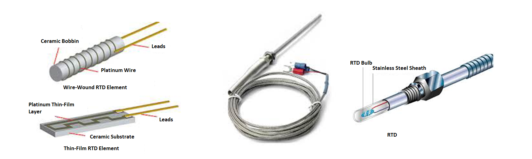
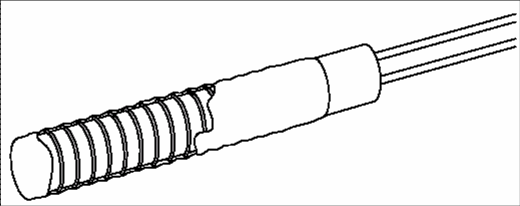
RTD Elements
- Wire Wound Element
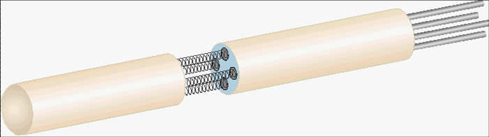
- Inner Coil Element
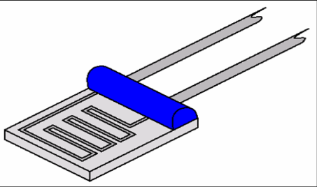
- Thin Film Element
Precise lengths of wire are wrapped around a ceramic mandrel, then inserted inside a ceramic shell which acts to support and protect the wire windings.
Wires are coiled then slid into the holes of a ceramic insulator. Some manufacturers backfill the bores with ceramic powder after the coils are inserted. This keeps the coils from shorting against each other.
Metallic ink is deposited onto a ceramic substrate. Lasers then etch the ink to provide a resistance path. The entire assembly is encapsulated in ceramic to support and protect.
This type is less expensive and has much faster response time than wire wound element.
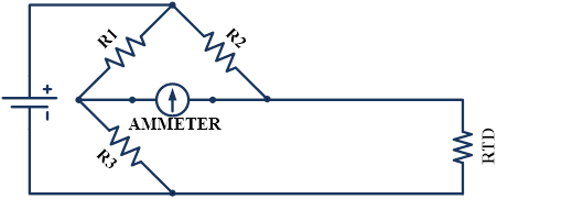
Wheatstone bridge
The most common method for measuring the resistance of an RTD is to use a Wheatstone bridge circuit.
In a Wheatstone bridge, electrical excitation current is passed through the bridge, and the bridge output current is an indication of the RTD resistance.
RTD Accuracy
Error or inaccuracy for Class A sensor is ±0.03ºC or 0.01% of span and for Class B sensor is about ± 0.3ºC or 0.12% of span.
Considering the whole measuring system inaccuracy inclusive of transmitter's electronic parts error, the total error or inaccuracy for Pt100 RTD is about 0.15% of span.
RTD Element Wiring Configuration
The basic RTD element is a 2-wire device which the two ends of the element are connected to two lead wires, then these lead wires will be connected to copper wires for extension.
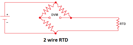
Considering these lead wires resistance, the above circuit accurate schematic would be as the following:
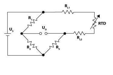
These lead wires resistance can drastically reduce the accuracy of the temperature measurement.
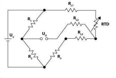
For compensating this affect, 3-wire configuration can be used and the resistance of lead wires will placed on the opposite legs of 3-wire Wheatstone bridge, therefore their impedance effects will be cancelled.
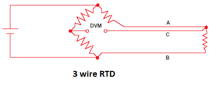
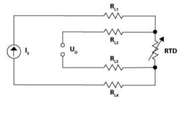
The accurate schematic of 3 wire RTD measurement would be:
4-wire configuration provides more compensation, hence full accuracy will be achieved.
In this 4-wire configuration, the output voltage read in the bridge is directly proportional to the RTD resistance and is insensitive to the length of lead wires.
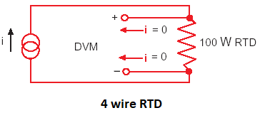
The accurate schematic of 4 wire RTD measurement would be:
4-Wire RTD is more accurate and expensive in comparison to 3-wire RTD.
4-wire RTD is used in laboratory applications and calibration devices.
RTD Common application
RTDs are often used as temperature transmitter in different industries for temperature measurement with 4~20mA output for low and middle temperatures.
The most common and proper RTD for most of industrial applications such as Oil & Gas, Petrochemical and power plants, with an acceptable accuracy and expense is 3-wire PT100.
RTDs and T/Cs comparison table
| Comparison Item | RTD | Thermocouple |
|---|---|---|
| Temperature Range | -328°F to 1562°F | -310°F to 3308°F |
| Accuracy | ±0.001°F to 0.1°F | ±1°F to 10°F |
| Response Time | Moderate | Fast |
| Stability | Stable over long periods (0.1% error / 5 yr) | Not as stable (1°F error / 1yr.) |
| Linearity | Best | Moderate |
| Sensitivity | High | Low |
| Vibration applications | Poor | Good |
Thermistor
Thermistors are temperature sensing devices that are similar to RTD’s in that their resistance changes as temperature changes.
There are two types of thermistors:
- NTC(Negative Temperature Coefficient) thermistors
- PTC(Positive Temperature Coefficient) thermistors
The resistance of NTC thermistors decreases with increasing temperature and the resistance of PTC thermistors increases with increasing temperature.
NTC thermistors are more sensitive than PTC thermistors.
NTC thermistors are more often used than PTC thermistors in temperature measuring applications.
Thermistors can be an inexpensive alternative to RTD’s when temperature ranges are below 150°C.
Thermistors can be used from temperatures of –80°C to 300°C.
Thermistors are very sensitive (up to 100 times more than RTDs and 1000 times more than thermocouples) and can detect very small changes in temperature. They are also very fast.
Due to their speed and sensitivity, they are used for precision temperature control and any time very small temperature differences must be detected.
Because of very large resistance, lead wire error is not significant, therefore 3-wire or 4-wire bridges are not used with thermistors.
NTC thermistors are made of ceramic semiconductor material (metal oxides) such as oxide of Nickel, Manganese, Copper, and Zinc…
PTC thermistors are made of silicon, barium, lead…
The change in thermistor resistance with temperature is very non-linear.
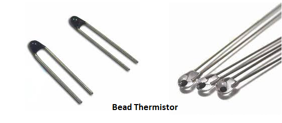
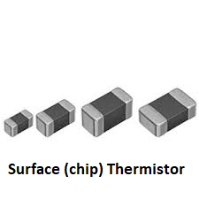
Thermistor element types
Most common type of thermistors elements are Bead and Surface (Chip) type; other types such as Washer, Disc and Rod are also available.
Thermistor accuracy
Inaccuracy of thermistors generally is between 0.006 ~ 0.6ºC and if calibrated 0.003ºC.
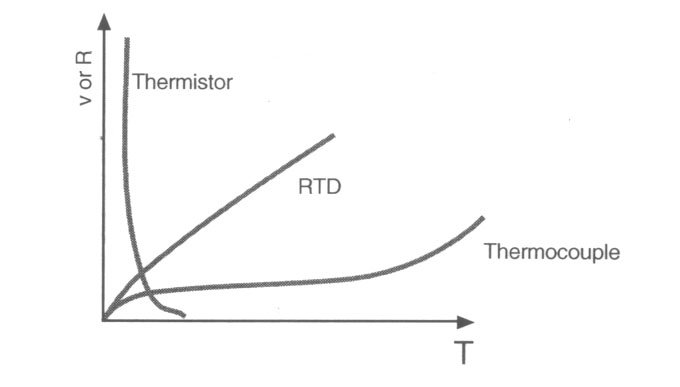
Linearity Comparison
The following figure shows that RTD is the most linear temperature measuring device in comparison to Thermocouple and Thermistor.
Therefore in control loops RTDs are used as temperature transmitters to send an analogue signal (4~20 mA) to the control system.
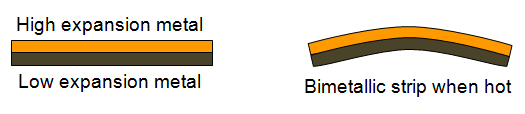
Bimetallic Thermometers
Metals volume changes with temperature and coefficient of this change is different from one metal to another.
This is the basic principle for bimetallic thermometers function.
If two different straight metal strip are bounded together and heated, the bounded strip will bend toward the side of the metal with lower expansion rate.
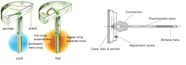
This motion can be amplified by providing the wounded strip in form of spiral or a helix.
Bimetallic thermometers are generally used for local indication as temperature gauges.
The helix bimetal moves axially as it winds and unwinds with heat and cold.
This movement causes the swirl movement of the pointer which is fastened to the end of the helix.
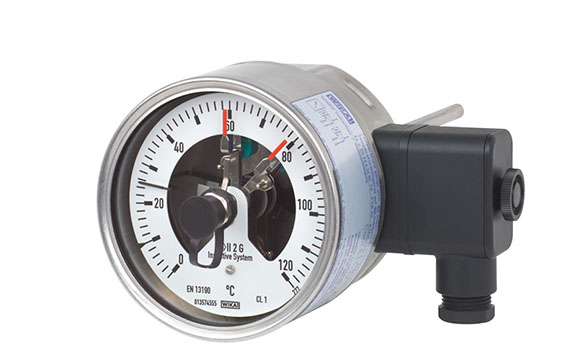
Bimetallic thermometers can also be used as a temperature switch, that the helix movement at a specific point, which is representative of a specific temperature, closes/opens a contact of a switch.
In some cases we can have Temperature Indicator Switch, that both mentioned functions as an integrated device.
It indicates the temperature the same as temperature gauge and also has a switch which can be adjusted to set point temperature.
The advantages of bimetallic thermometers are low cost and simplicity.
The disadvantage of bimetallic thermometers is that their calibration could be changed due to rough handling.
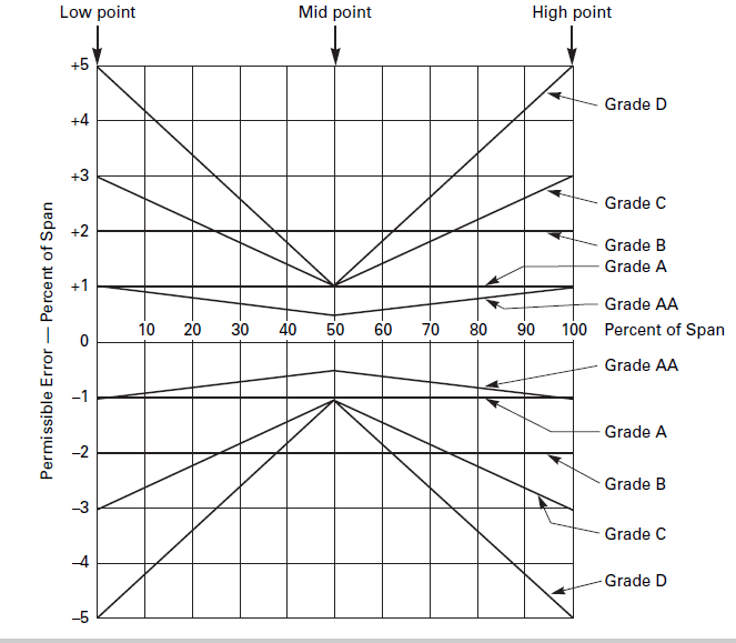
Bimetallic thermometers accuracy
According to ASME B.40.200, there are 4 accuracy grades defined for bimetallic thermometers:
Grades A,B,C,D and AA.
Accuracy for grade A is ±1% of full span.
Filled Thermal Systems
The basic filled thermal system is the clinical thermometer which is consist of glass bulb filled with Alcohol or Mercury and a scaled glass stem.
As the bulb temperature increases, the filled liquid will expand and goes high in the scaled stem.
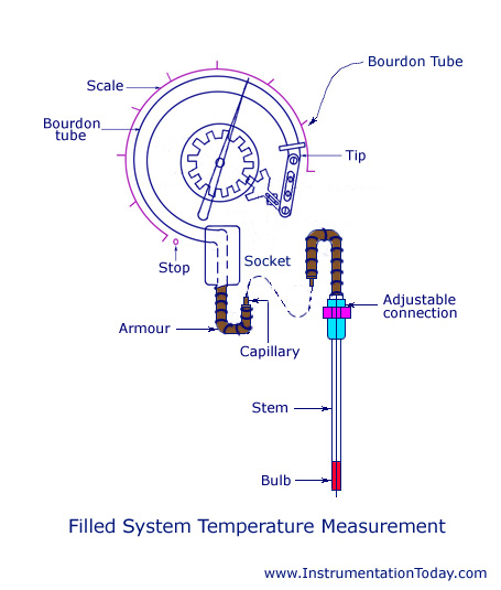
Industrial filled system thermometers are similar to a pressure gauge connected to a filled bulb with small bore tubing.
The bulb could be filled with liquid, gas or vapour.
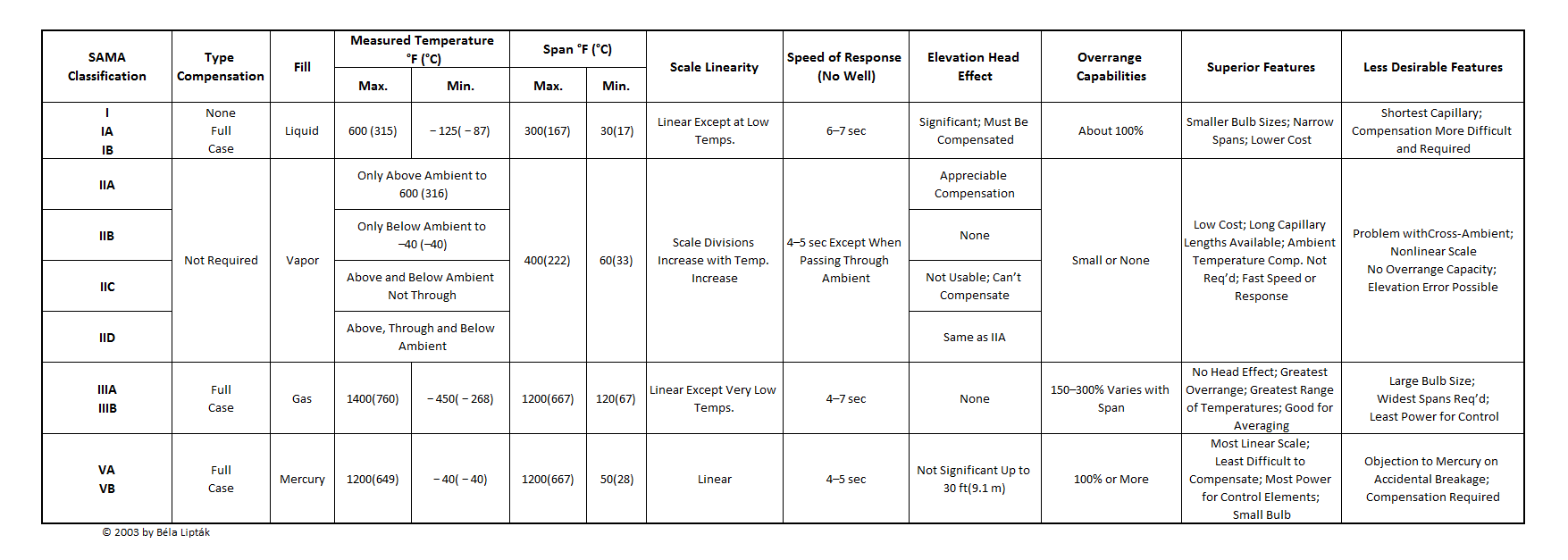
Filled thermal system classification
Filled thermal system are classified according to the filled material.
- Class I: Liquid Filled
- Class II: Vapour Filled
- Class III: Gas Filled
Please note that mercury filled thermometers are no longer used due to health concerns.
The following table provides a good comparison of filled thermal systems classes:
One important point that shall be concerned about the filled system thermometers is their response time.
Filled system response time depends on the filled material, shape of the bulb, capillary diameter…
Gas and vapour filled thermometers have faster response time in comparison with liquid filled type.
The response speed doubles with doubling the bulb diameter.
Also if the bulb is installed in the thermowell then the response time will exceed more.
Liquid Filled thermal systems
The filled liquid is usually xylene (C8H10) which is an inert hydrocarbon.
The system pressure shall be more than the filled liquid vapour pressure to avoid forming of bubbles of vapour in capillary tube.
Minimum range of thermometer is defined according to freezing point of the filled liquid and the maximum range is defined based on the temperature at which the liquid is no longer stable.
Over range protection of the liquid filled thermometer is usually around 100% of span.
Vapour Filled thermal systems
In this type bulb and capillary are filled with both liquid and vapour form of a medium.
The system pressure is a function of vapour pressure of the filled fluid at the operating temperature.
The following fluids are usually used as filled medium for this type:
Methyl chloride, sulphur dioxide, butane, propane, hexane, methyl ether, ethyl chloride, ethyl ether, ethyl alcohol, and chlorobenzene.
For lower temperatures ethane with vapour pressure of 1.4 to 41 bars at temperature range of -73 to 29 ºC and for higher temperatures ethyl chloride with the same vapour pressure but at temperature range of 38 to 177 ºC can be used.
The maximum temperature is limited to critical point of the filled fluid while the minimum limit is consequence of the loss of reading sensitivity, as the vapour pressure changes less per unit temperature change at low temperatures.
The over range limit of the vapour filled systems is small because the vapour pressure tends to rise exponentially with temperature.
Gas Filled thermal systems
The operating principle for gas filled systems is that in a perfect gas confined to a constant volume the pressure is proportional to the absolute temperature.
The used gases are not perfect however the variances are small enough that the measurement of pressure can be used to indicate temperature.
Nitrogen is the favourite gas for this systems because it is inert gas and inexpensive, but for low temperature ranges Helium is preferred.
Low side of temperature range is limited by the critical temperatures of the filing gas (usually nitrogen or helium).
The high side of temperature range depends on the bulb material.
The maximum span can be 1200°F (667°C), and is limited only by nonlinearities due to mass flow from the bulb.
The minimum span is limited by the pressure at which the Bourdon tube becomes overstressed.
The speed of response of gas filled systems is usually good.
Infrared Thermometers
Physicists abandoned that heat, as a form of energy, transfers from one material to another by conduction, convection, radiation and phase change (Evapotranspiration), because kinetic energy or heat wants to be at equilibrium.
Radiation is one of the most important ways of heat transfer. Earth gets energy from the sun by radiation.
All moving charged particles of an object emit electromagnetic radiation that travels at speed of light (299,792 kilometers per second).
When this emitted electromagnetic wave hits another particle, this radiation is received as kinetic energy.
Wavelength of the emitted electromagnetic wave from an object is proportional to the object temperature.
As the temperature rises, the wavelength goes down and the frequency goes high.
So if we measure the wave length of emitted electromagnetic wave of and object by pyrometer, we can find out the object temperature.
For extremely hot objects, the wavelength is in range of x-ray and omega.
Infrared (IR) wavelength is 2 to 20 µm which means that we can measure the objects temperature from approximately -100 to 1500 ºC with an IR wavelength meter device.
For industrial applications measuring temperature is usually in IR range. That’s why the pyrometers are called IR Thermometers in industry.
Pyrometer design categories
- Wide-band or Total radiation
- When full spectrum of 0.3 to 15 µm is used.
- Narrow-band
- When a single small segment of spectrum is used. If visible spectrum is used, it is called optical pyrometer.
- Ratio or two-color
- When ratio of intensities of two wavelengths is detected.
- IR
- When IR spectrum (0.7 to 15 µm) is used.
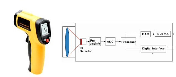
How does the IR thermometer work?
IR thermometer uses an optical system including of collector lens, filter and a detector.
This optical system collects IR energy from the object, through a filter and focuses it on the detector.
The detector converts the received energy to electrical signal that specifies the absolute temperature.
IR thermometer detector types
There are two types of detectors: Thermal detectors and Photo detectors.
Photo detectors have faster response and they are more sensitive to wavelength, but they are affected by the detector temperature, therefore they require cooling device.
For selecting the proper measuring devise the following items could be considered and discussed with the manufacturer:
- Target temperature
- Target material and it's emittance
- View field, angle of observation and distance
- Detector type and sensitivity
- Ambient temperature
- Atmospheric condition between device and the target
IR thermometer application
IR thermometer is used in application which non-contact and portable thermometer is required.
Extremely hot targets like furnaces or high voltage targets like power transformers bushings are the most common applications for IR thermometers.
Accuracy
IR thermometer inaccuracy is generally 0.05 to 2% of reading. Under laboratory conditions precision can be 0.1ºC.
Temperature instruments selection summarized tips
- For medium range temperature transmitters RTD Pt-100 is commonly used in industries.
- For high temperature transmitters Thermocouple element is commonly used.
- For Temperature gauges bimetallic thermometers are used.
- For Temperature switches most commonly used element is Thermistor due to fast response and sensitivity.
- Due to the following reasons in most of project specifications filled type thermometers are prohibited or not recommended:
- slow response (approximately 20 seconds in a thermowell)
- narrow spans are not available
- not suitable for high temperatures
- zero and span adjustments interact so they are difficult to calibrate
- elements are not repairable
The thermometers can be compared based on the following factors
- Cost
- Thermocouples are cheapest by far, followed by RTDs
- Accuracy
- RTDs,then thermistors
- Sensitivity
- Thermistors
- Speed
- Thermistors
- Stability at high temperatures
- Not thermistors
- Size
- Thermocouples and thermistors can be made quite small
- Ruggedness
- Thermocouples are best in harsh situations
- Non- contact applications
- IR thermometers
Thermowell
Thermometer element is installed inside thermowell in order to be protected against mechanical damages and corrosion.
Also thermowell permits thermal elements to be removed for calibration, maintenance or replacement during operation without empting the vessel, tank or pipe line.
In case of using portable thermometers, thermowell has an essential rule.
API RP 551:
Installing temperature elements in thermowells adds time lag and errors to the measurement. However, by using a spring loaded fitting so the element firmly contacts the bottom of the thermowell the measurement lags and errors are reduced. For temperatures above 290 °C (550 °F), N07718 springs should be considered.
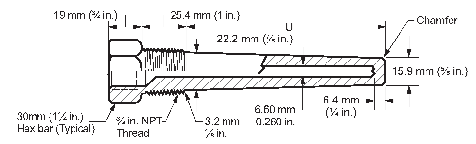
Thermowell connection type
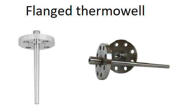
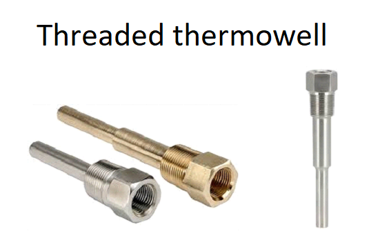
Thermowell connection to process equipment could be flanged, Van stone or threaded.
Welded connection is not recommended, due to permanent connection to the piping and process equipment, which may cause problems during maintenance.
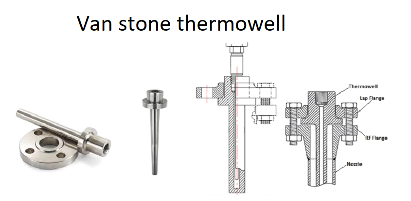
Van stone connection is a kind of flanged connection that flanged is not welded to the thermowell.
This design provides the advantage of using the same thermowell for different class flanges (150#,300#,600#...) , but with longer than standard studs.
In some industries such as oil & gas industry, 1-1/2 " flange with minimum rating of 300# is specified in design specifications for thermowell connection and threaded connection is prohibited.
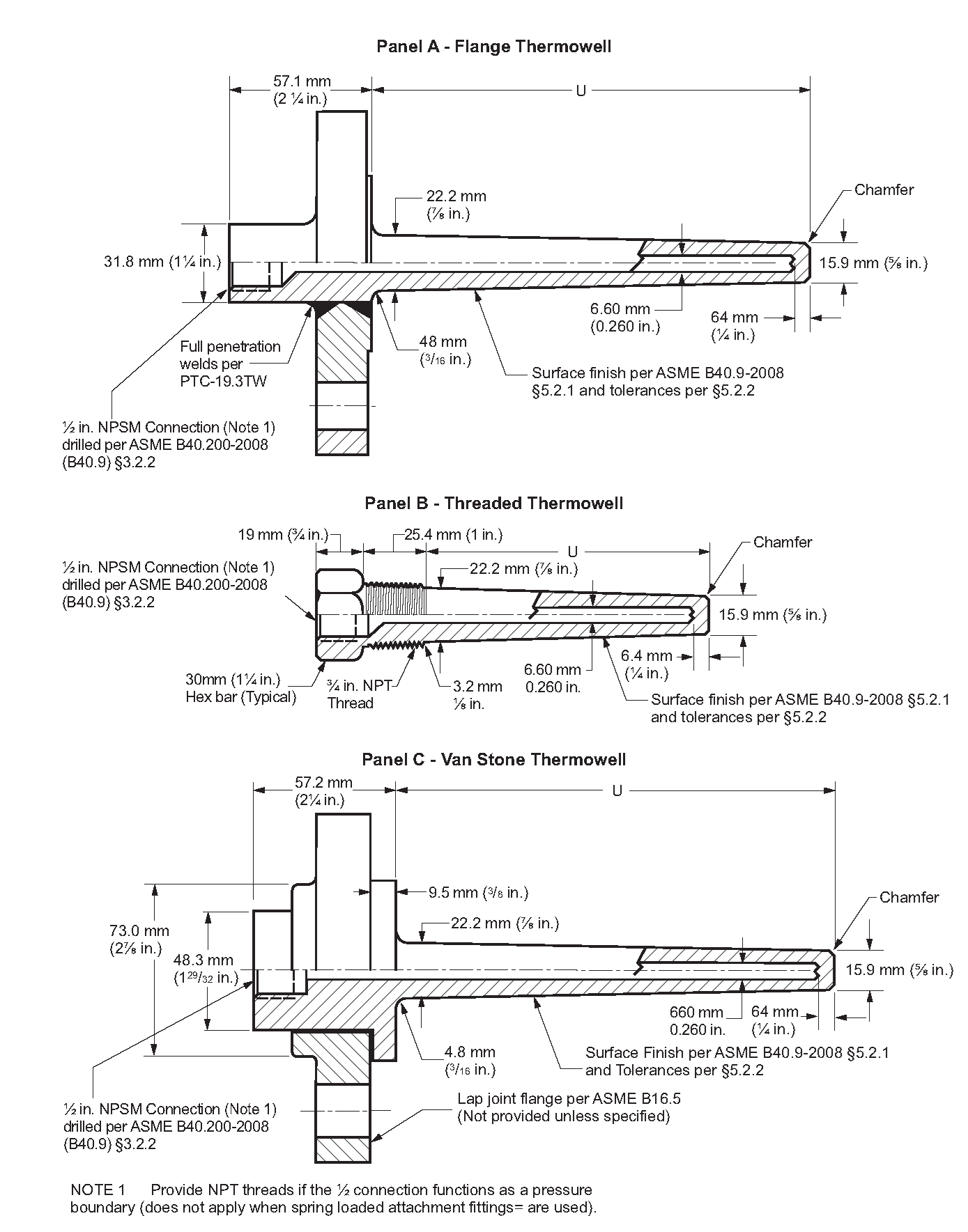
The following detail from API RP 551 could be very useful.
Thermowell material
Temperature and corrosion of service should be considered for thermowell material selection, otherwise damaged thermowell would be weak point of piping system and source of leakage.
For sour services, materials with more than 13% of chromium component are corrosion resistant and suitable.
AISI 316 Stainless Steel is a wise selection for corrosive services with temperature range of -254 to 816°C.
Corrosion resistance of AISI 316 Stainless Steel is more than AISI 304 Stainless Steel, due to more amount of molybdenum component in AISI 316 Stainless Steel.
For services that contain an aggressive species such as chloride (Cl-), similar to seawater are source of pitting corrosion. Pitting Resistance Equivalent Number (PREN), mechanical specification and cost of the material should be considered for material selection for such services.
Austenitic Stainless Steels (316SS, 304SS, 321SS …) are not proper for seawater and services containing chlorides, due to low PREN.
Materials with a PREN greater than 40 are very resistant to seawater, hence most of Nickle based alloys (Monel, Inconel, Incoloy ...) and Duplex & Superduplex alloys are suitable for seawater services.
Considering cost and mechanical properties Monel 400 (N04400) is the best selection for thermowell material in seawater services.
NACE International Materials Requirements MR0175 is a great reference of material selection for sour and corrosive services.
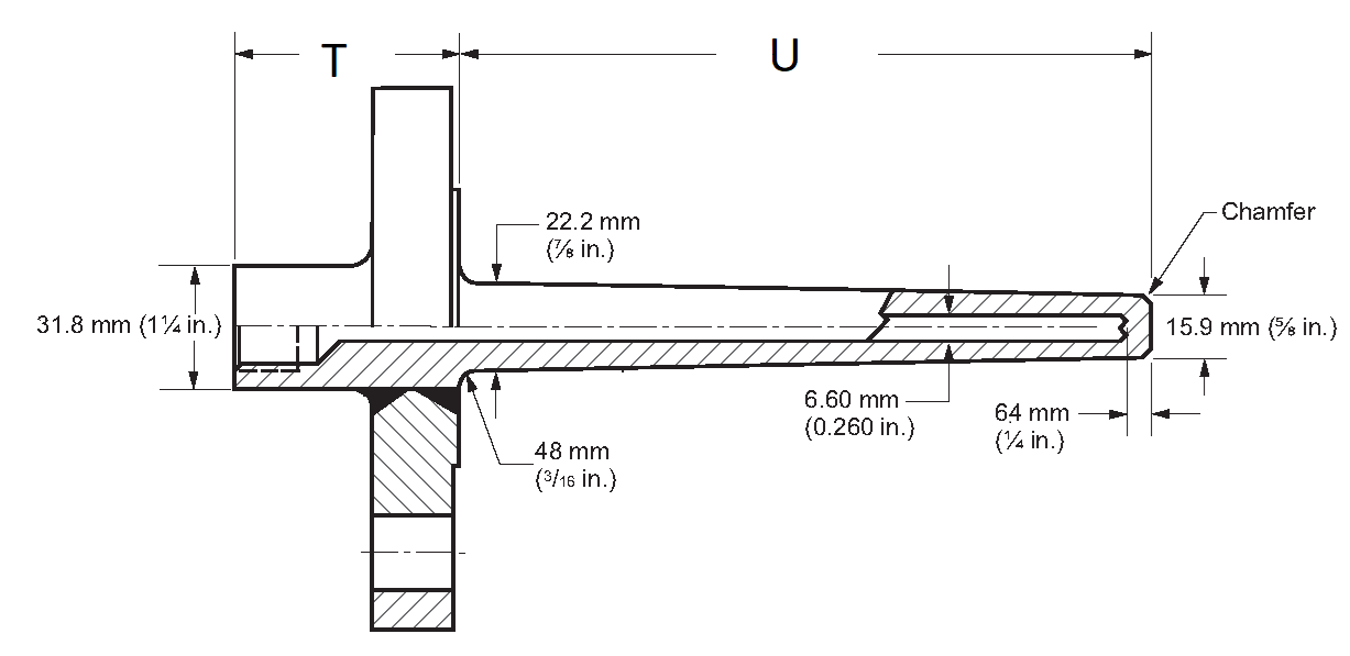
Thermowell construction
Thermowells shank construction types are:
- Tapered
- Straight
- Stepped
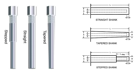
Thermowell protects the temperature element from mechanical and corrosion damages, but increases the response time of the measuring system.
In addition, in pipelines, thermowells are facing stresses and strains produced by process flow.
In order to reduce the effect on response time and mechanical stresses and forces on the thermowell, it is proper to reduce the thermowell tip as much as possible.
Therefore tapered and stepped shank thermowells are used for pipeline applications.
Stepped type could be used for very short thermowells, while tapered type could be used for longer thermowells.
Straight type thermowell could be used in low pressure and low velocity applications such as storage tanks.
It is recommended to use tapered shank thermowell in most of applications due to grate strength and vibration resistance.
After selecting the thermowell construction type, construction technique should be considered which has a very important role in thermowell lifetime.
Typically, there are three construction techniques for thermowell manufacturing:
- Drilled
- Build-up
- End-Close Tube
Build-up and End-Close Tube constructions are not suitable for harsh industrial services in which thermowell is subject to turbulent flows and erosion.
Drilled construction thermowell is recommended for industrial applications.
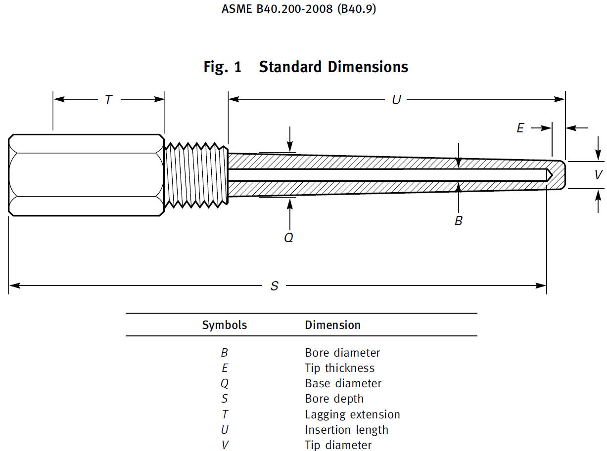
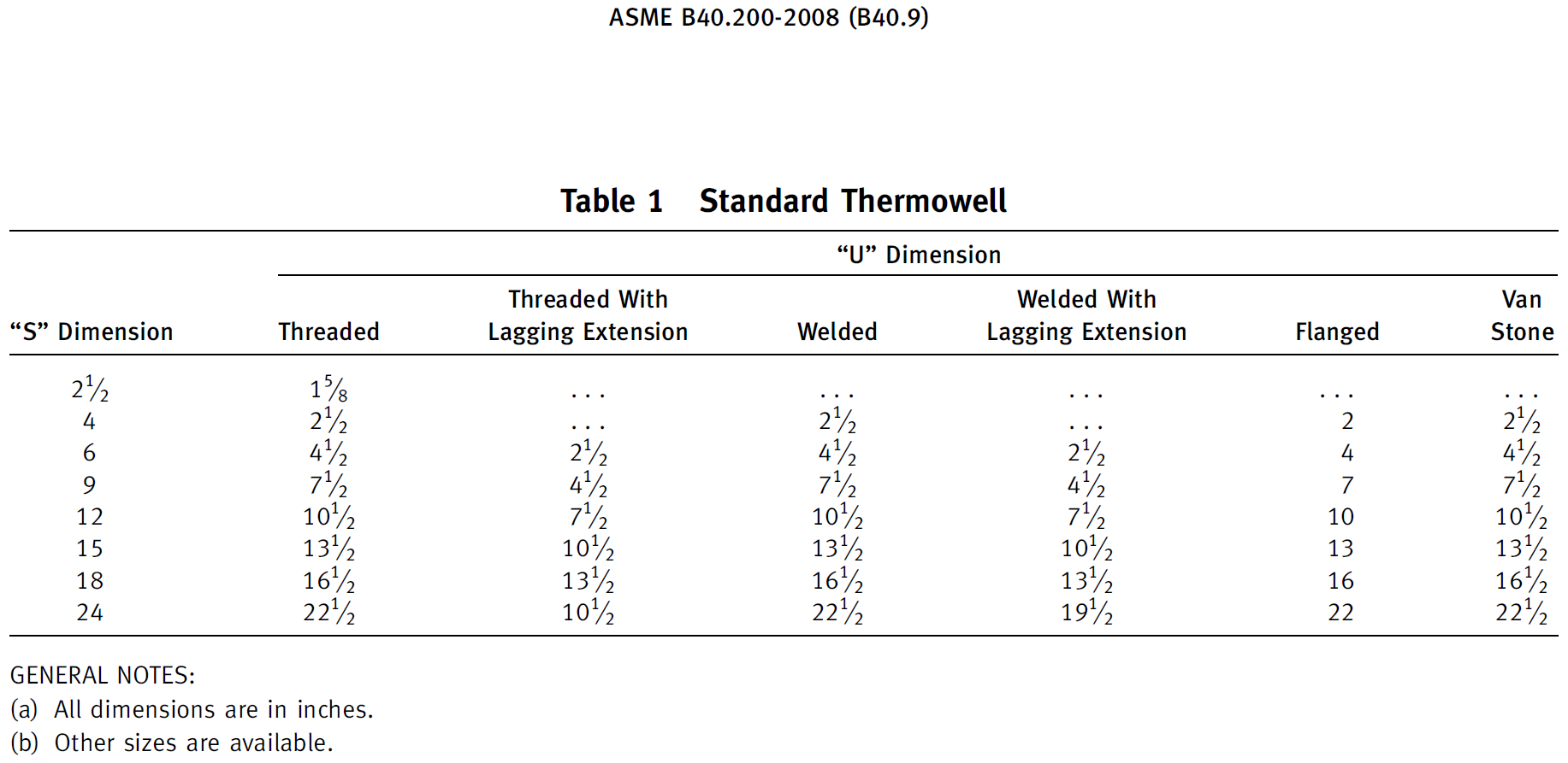
ASME B40.9 provides detail and dimensions for standard thermowell.
In order to reduce time lag and errors of measurement, thermowell tip should be located in middle third of pipeline.
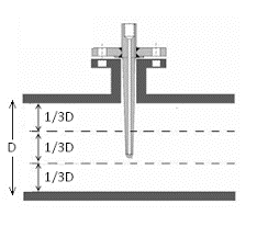
It means that thermowell "U" length should be calculated considering pipe diameter and nozzle length.
For pipelines less than 4", pipeline should be expanded to 4" for thermowell installation.
Nozzle length is generally provided by piping department in piping installation detail drawing document.
Typically, length of flanged nozzles is 150mm from pipe top, up to the flange face.
For thread connection, the thredolet length is about 35mm.
It is absolutely essential to finalize nozzle length with piping department before U length calculation.
Here it is our recommendation for thermowell U length considering the above mentioned nozzle length.
Flanged thermowell dimensions (Nozzle length=150mm)
| Line size inch(mm) | U length (mm) for Rating ANSI 300,600,900,1500 & 2500# | T length (mm) for Rating ANSI 300,600# | T length (mm) for Rating ANSI 900,1500# | T length (mm) for Rating ANSI 2500# |
|---|---|---|---|---|
| 4" (100mm) | 200 | 75 | 85 | 100 |
| 6" (150mm) | 220 | 75 | 85 | 100 |
| 8" (200mm) | 250 | 75 | 85 | 100 |
| 10" (250mm) | 250 | 75 | 85 | 100 |
| 12" (300mm) | 300 | 75 | 85 | 100 |
| 14" (350mm) | 300 | 75 | 85 | 100 |
| 16" (400mm) | 350 | 75 | 85 | 100 |
| 18" (450mm) | 350 | 75 | 85 | 100 |
| 20" (500mm) | 350 | 75 | 85 | 100 |
| 24" (600mm) | 350 | 75 | 85 | 100 |
| ≥28"(≥700mm) | 500 | 75 | 85 | 100 |
| on vessels | 500 | 75 | 85 | 100 |
Note: U length for flanged thermowells may not be more than 500mm, because of the stresses, strains and vibrations that may cause thermowell breakage.
Threaded thermowell dimensions (Therdolet length=35mm)
| Line size inch(mm) | U length (mm) |
|---|---|
| 4" (100mm) | 75 |
| 6" (150mm) | 75 |
| 8" (200mm) | 100 |
| 10" (250mm) | 100 |
| 12" (300mm) | 150 |
| 14" (350mm) | 150 |
| 16" (400mm) | 200 |
| 18" (450mm) | 200 |
| 20" (500mm) | 250 |
| 24" (600mm) | 250 |
| ≥28"(≥700mm) | 300 |
| on vessels | 300 |
Note:U length for threaded thermowells may not be more than 300mm, because of the stresses, strains and vibrations that may cause thermowell breakage.
The above U length recommendation is premilinary and should be confirmed and finalized by thermowell manufacturer base on wake frequency calculation which is described in the following.
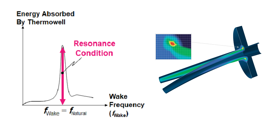
WAKE Frequency calculation
As the flow of the medium in the pipeline passes by the thermowell, it forms a turbulent wake (Von Karman trail), that generates a vibration in the thermowell proportionate to the diameter of the thermowell and velocity of the medium.
If frequency of this vibration reaches the natural frequency of thermowell this may result in the shearing-off of the thermowell into the process.
Performance Test Code, ASME PTC 19.3 TW, establishes a mechanical design standard for reliable service of thermowells in a broad range of applications and its design rules ensure the mechanical integrity of the thermowell.
Thermowell manufacturer should calculate wake frequency according to ASME PTC 19.3 TW and it should be less than 0.8 of natural frequency.
If the calculated frequency exceeds 0.8 of natural frequency, then the following solutions may be able to reduce the wake frequency:
- Using support collar
- Reduce insertion length into pipe
- Changing thermowell material
- Increasing flange rating
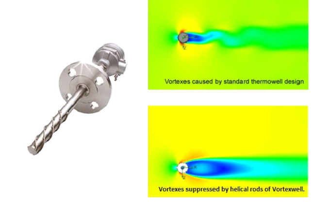
- Using an Okazaki Vortexwell
ASME PTC 19.3 TW does not support and recommend using support collar as it does not assure a rigid support plane and so the thermowell shank will be subjected to a hammering effect brought on by the constant vibration.
Reducing insertion length thermowell is a very good and economic solution as long as thermowell tip is in middle third of pipe so measuring accuracy is not affected.
Changing thermowell material should be done very wisely considering cost, medium specifications, corrosion resistance, design pressure and design temperature of the line in order not to deviate project specifications
Changing the material is not always the best solution.
Increasing flange rating could be the best solution due to increasing mechanical strength of the thermowell specially in the conjunction with the flange.
After Monju Nuclear Power Plant sodium leakage on December 8, 1995 in Japan, caused by breakage of a thermowell on sodium coolant pipe line, Okazaki MFG innovated a new design of thermowell (Vortexwell) with helical rods that suppresses resonance with Kármán vortices.